Polyaxial pedicle screw having a rotating locking element

Inactive Publication Date: 2005-01-11
K2M
View PDF5 Cites 374 Cited by
  • Summary
  • Abstract
  • Description
  • Claims
  • Application Information

AI Technical Summary

Benefits of technology

Once the rods are in the rod receiving channels, the surgeon proceeds to move each locking element into the locked position by rotating the locking element. As the locking element is moved to the locked position, the permissive surface, of the locking element, that is presented to the compression surface of the head of the screw when the locking element is in the unlocked position, is removed and the compression surface is increasingly presented with the confrontational surface. This causes the curvate proximal portion of the head of the screw to be increasingly compressed toward the bore until the head is immovable in the seat of the coupling element. Ultimately, the compression surface seats in the recess and thereby is biased against retreat from the recess. This prevents accidental reverse rotational slippage of the locking element from occurring and moving the locking element to the unlocked position.
In addition, as the locking element is moved to the locked position, the rod-receiving channel presented by the locking element when the locking e

Problems solved by technology

Genetic or developmental irregularities, trauma, chronic stress, tumors, and disease, however, can result in spinal pathologies which either limit this range of motion, or which threaten the critical elements of the nervous system housed within the spinal column.
It has been identified, however, that a considerable difficulty is associated with inserting screws along a misaligned curvature and simultaneously exactly positioning the coupling elements such that the rod receiving portions thereof are aligned so that the rod can be passed therethrough without distorting the screws.
Attempts at achieving proper alignment with fixed screws is understood to require increased operating time, which is known to enhance many complications associated with surgery.
Often surgical effor

Method used


Image

  • Polyaxial pedicle screw having a rotating locking element
  • Polyaxial pedicle screw having a rotating locking element
  • Polyaxial pedicle screw having a rotating locking element

Examples


Embodiment Construction

While the invention will be described more fully hereinafter with reference to the accompanying drawings, in which particular embodiments and methods of implantation are shown, it is to be understood at the outset that persons skilled in the art may modify the invention herein described while achieving the functions and results of this invention. Accordingly, the descriptions which follow are to be understood as illustrative and exemplary of specific structures, aspects and features within the broad scope of the invention and not as limiting of such broad scope.

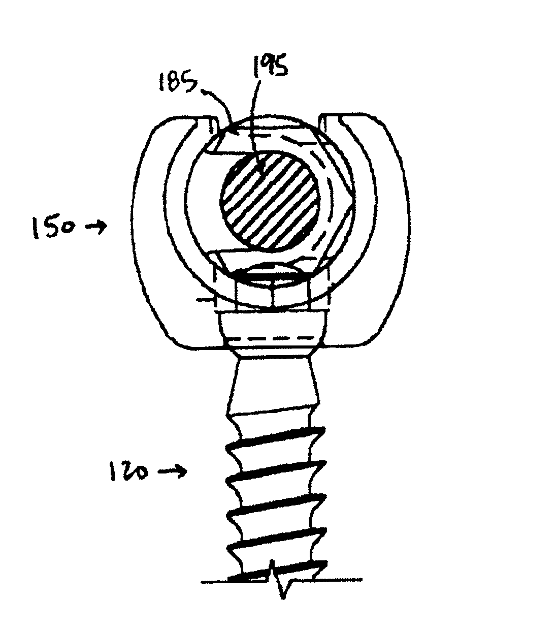
In an embodiment, the invention provides a screw and coupling element assembly for use with an orthopedic rod implantation apparatus. The assembly includes a securing element such as, for example, a screw, that has a head and a shaft that extends from the bead. Other securing elements can include, for example, lamina hooks and sacral blocks.

Accordingly, FIG. 4a illustrates a side view of a screw 120 suitable for use in the in...


PUM


Abstract

A screw and coupling element assembly for use with an orthopedic rod implantation apparatus includes a screw with a head and a shaft extending from the head, a coupling element with a seat within which the head is seatable such that the shaft protrudes from the coupling element, and a locking element mateable with the coupling element and when mated is selectively movable through a plurality of positions including unlocked and locked positions. When in the unlocked position, the locking element presents a rod-receiving channel and the head is movable in the seat such that the shaft is directable in a plurality of angles relative to the coupling element. When in the locked position, a rod disposed within the rod-receiving channel is fixed relative to the coupling element and the head is immovable in the seat such that the shaft is fixed at an angle relative to the coupling element.

Description

FIELD OF THE INVENTIONThe invention relates generally to screws and coupling element assemblies for use with orthopedic fixation systems. More particularly, the invention relates to a screw and coupling element assembly, for use with an orthopedic rod implantation apparatus, that includes a locking element that simultaneously locks a head of the screw within a seat of the coupling element so that a shaft of the screw is fixed at an angle relative to the coupling element and a rod, of the orthopedic rod implantation apparatus, disposed within a rod-receiving channel of the locking element is fixed relative to the coupling element.BACKGROUND OF THE INVENTIONThe bones and connective tissue of an adult human spinal column consists of more than twenty discrete bones coupled sequentially to one another by a tri-joint complex which consist of an anterior disc and the two posterior facet joints, the anterior discs of adjacent bones being cushioned by cartilage spacers referred to as interve...

Claims


Application Information

Patent Timeline
IPC IPC(8): A61B17/88A61B17/70A61B17/86A61B17/68
CPCA61B17/7032A61B17/7037A61B17/7082A61B17/7091A61B17/7076A61B17/861
Inventor RALPH, JAMES D.TATAR, STEPHEN
Owner K2M
Why Eureka
Try Eureka