
Wind power generator having wind channeling body with progressively reduced section

a wind power generator and section technology, applied in wind energy generation, motors, electrical equipment, etc., can solve the problems of severe damage to wildlife, unfavorable visual impact, and noise produced by horizontal and vertical axis devices, and achieve high machine performance

Inactive Publication Date: 2005-01-11
GOMEZ GOMAR JOSEP LLUIS
View PDF59 Cites 77 Cited by
  • Summary
  • Abstract
  • Description
  • Claims
  • Application Information

AI Technical Summary

Benefits of technology

In addition, this use is performed in a markedly environmental-friendly way, since the wind power recovery of the improvements introduced is clean, quiet and with a high machine performance.

Problems solved by technology

As is known, today's horizontal axis devices stand in general at a considerable height and are located in very high areas and almost always in the very parting planes of mountain slopes, mountain ranges or massifs, with the consequent undesired visual impact.
They can also cause severe damage to wildlife, especially to flying species, due to their large blades.
Today's horizontal and vertical axis devices also produce a characteristic noise when the assembly blades are turning, which can become serious when considering the installation of a wind power plant with a large number of power devices.
Another additional problem of vertical axis devices, and also reduced with the incorporation of the present improvements, is that they require motorization in order to overcome the high breakaway torque.
P 9300316 “Wind Turbo Generator” presents a large hopper applied to a horizontal axis wind turbine so that it is also used with low speed winds, but due to such large hopper produces a significant visual and sound impact.

Method used


Image

  • Wind power generator having wind channeling body with progressively reduced section
  • Wind power generator having wind channeling body with progressively reduced section
  • Wind power generator having wind channeling body with progressively reduced section

Examples


Embodiment Construction

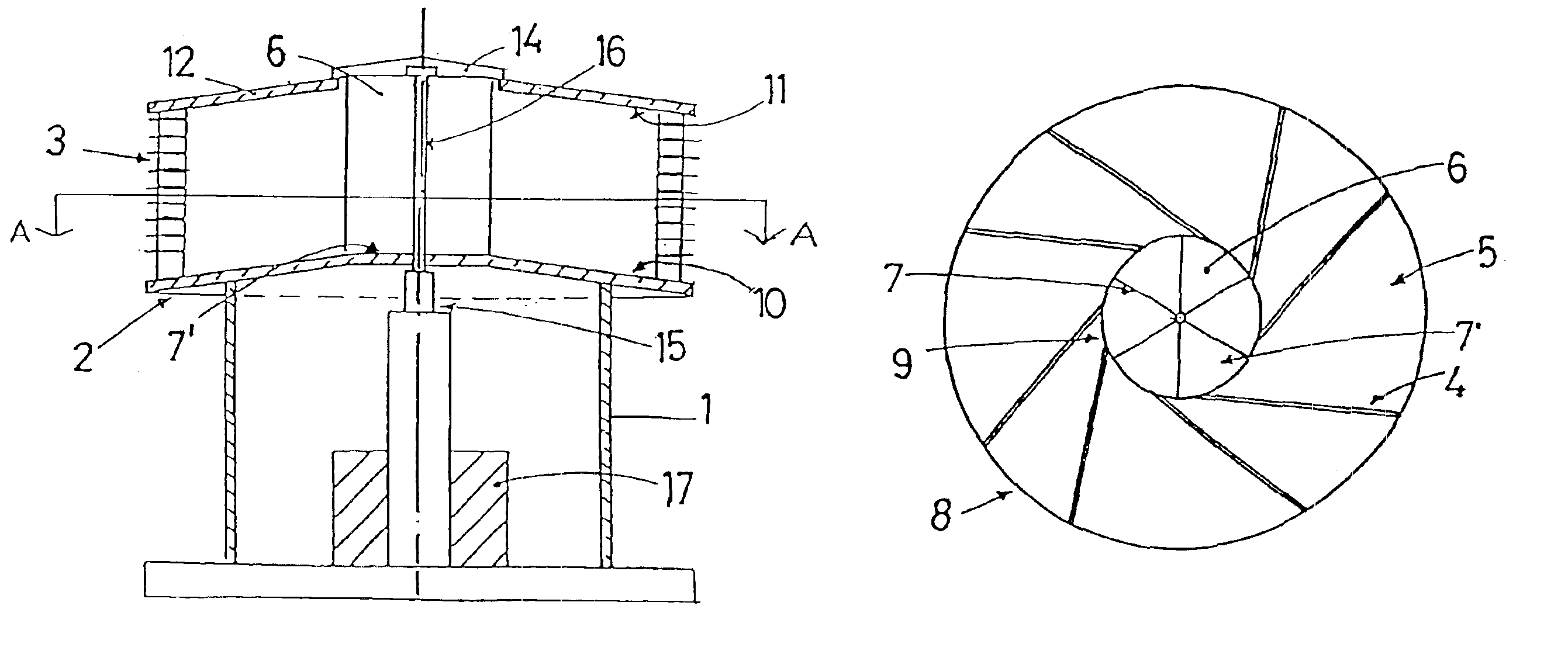
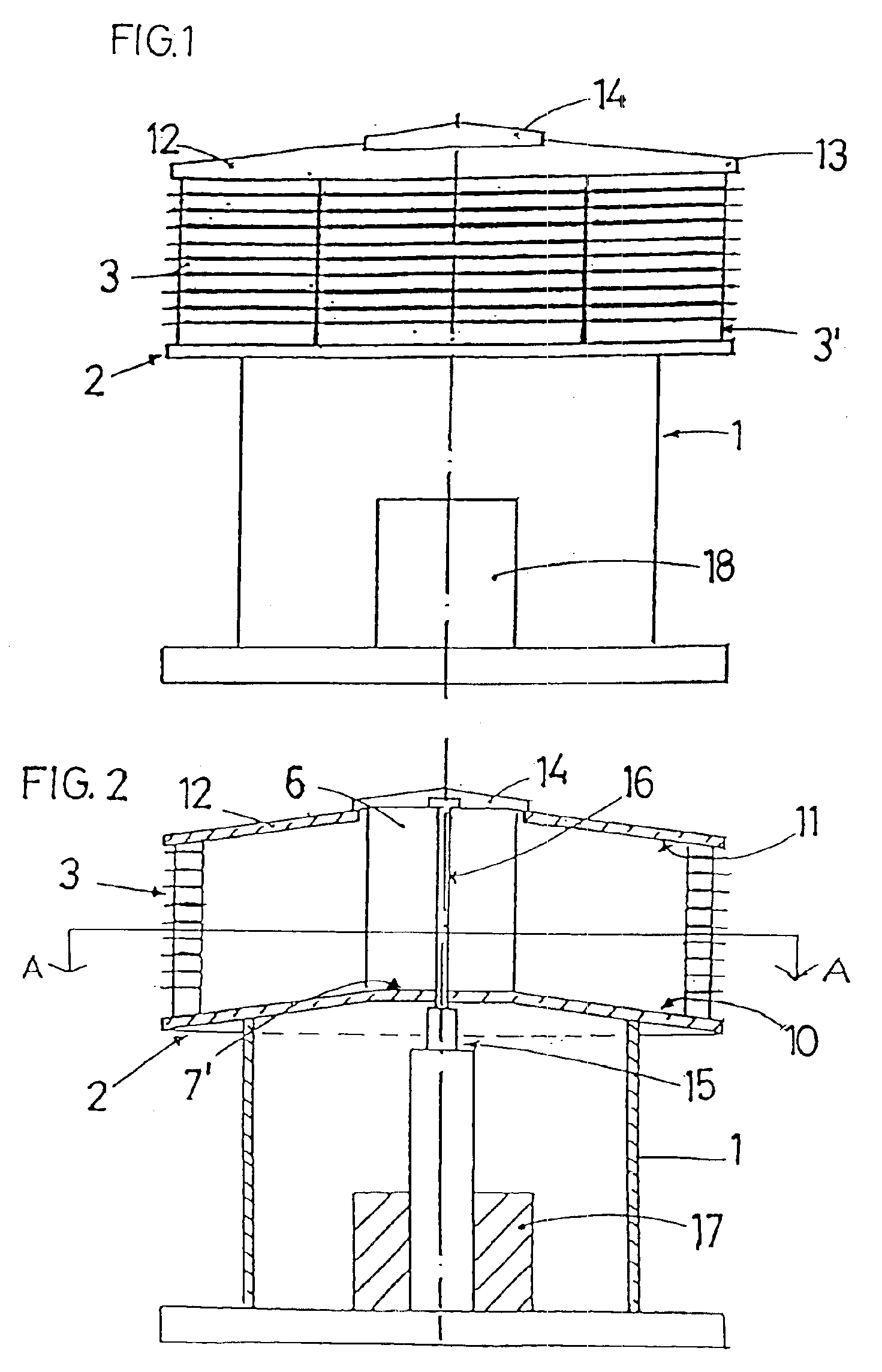
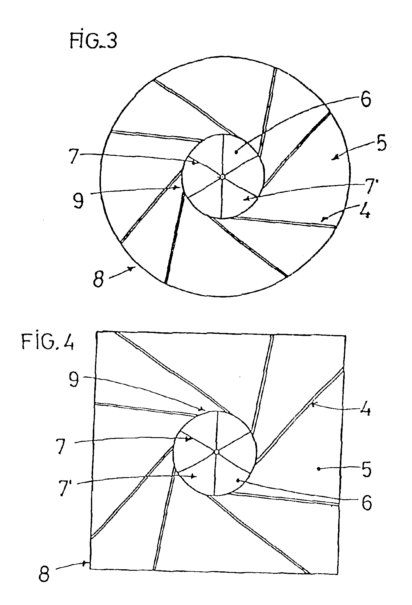
According to the drawings, the improvements introduced in the vertical axis wind power recovery devices comprise a reinforced concrete tower (1) on top of which there is located a wind channeling body (2) that has an open side face but delimited in its entire contour by adjustable blinds (3).

The wind channeling body (2) is umbrella-shaped and has a circular or polygonal plan as shown in FIGS. 3 to 7, with a surface area larger than the tower surface (1) and with a body height (2) standing, preferably, around 2.5 and 3 meters (8.2-10 ft).

The practical embodiment of said improvements shows, in principle, three alternatives according to the height that can reach the structure formed by the tower (1) and the wind channeling body (2).

A first alternative, with a structure between 10 and 15 meters in height, determined by the site where it will be installed and by the wind recovery expected.

A second alternative would be a structure between 5 and 10 meters in height, according to the same f...


PUM


Abstract

A wind power recovery device has a tower, a rotor arranged on the tower and including a plurality of blades rotatable under the action of wind, the rotor also having an axis for transmitting the rotation of the rotor to another apparatus, a wind channeling body provided with a series of walls which form channelings with a section which is progressively reduced from an entry side of the wind channeling body to an exit side of the channeling body toward the rotor to affect tangentially the blades of the rotor at a speed higher than at the entry side of the body, the wind channeling body having a side face, and a blind protecting the side face of the channeling body.

Description

TECHNICAL FIELDThe present invention relates to a wind power generator having a wind channeling body with a progressively reduced section.BACKGROUND OF THE INVENTIONIn relation to prior art, currently existing devices that are used to recover wind power and transform it into mechanical or electrical energy can be classified, according to its axis position, as horizontal axis or vertical axis, suffering both types from several disadvantages, sufficiently overcame by the improvements of the present patent.As is known, today's horizontal axis devices stand in general at a considerable height and are located in very high areas and almost always in the very parting planes of mountain slopes, mountain ranges or massifs, with the consequent undesired visual impact. They can also cause severe damage to wildlife, especially to flying species, due to their large blades. These negative factors are determinant for the installation of wind power plants nowadays, versus ecologist requirements. Im...

Claims


Application Information

Patent Timeline
Patent Type & Authority Patents(United States)
IPC IPC(8): F03D3/04F03D3/00
CPCF03D3/0409Y02E10/74Y02E10/728F03D9/25F03D15/10F03D13/22F03D3/0427
Inventor GOMEZ GOMAR, JOSEP LLUIS
Owner GOMEZ GOMAR JOSEP LLUIS
Learn More