Motor with brush and commutator, and electric apparatus using the same motor
a technology of electric motors and brushes, applied in the direction of current collectors, dynamo-electric components, windings, etc., can solve the problems of reducing the output of motors, and achieve the effects of reducing weight, preventing the reduction of a number of active conductors, and reducing shorts
- Summary
- Abstract
- Description
- Claims
- Application Information
AI Technical Summary
Benefits of technology
Problems solved by technology
Method used
Image
Examples
first exemplary embodiment
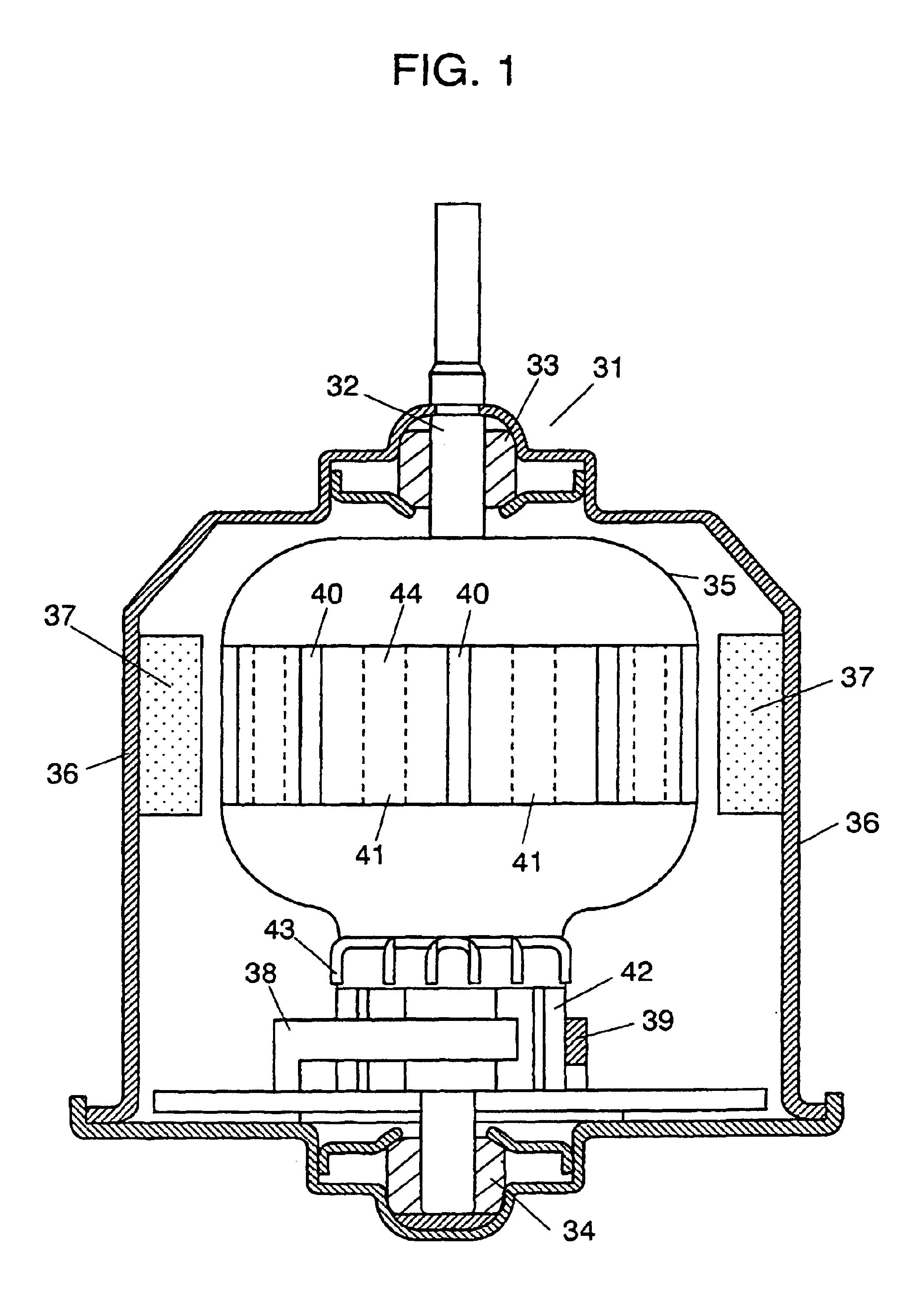
FIG. 1 shows a cross sectional view of a motor in accordance with the first exemplary embodiment of the present invention. In FIG. 1, motor 31 is constructed as follows:
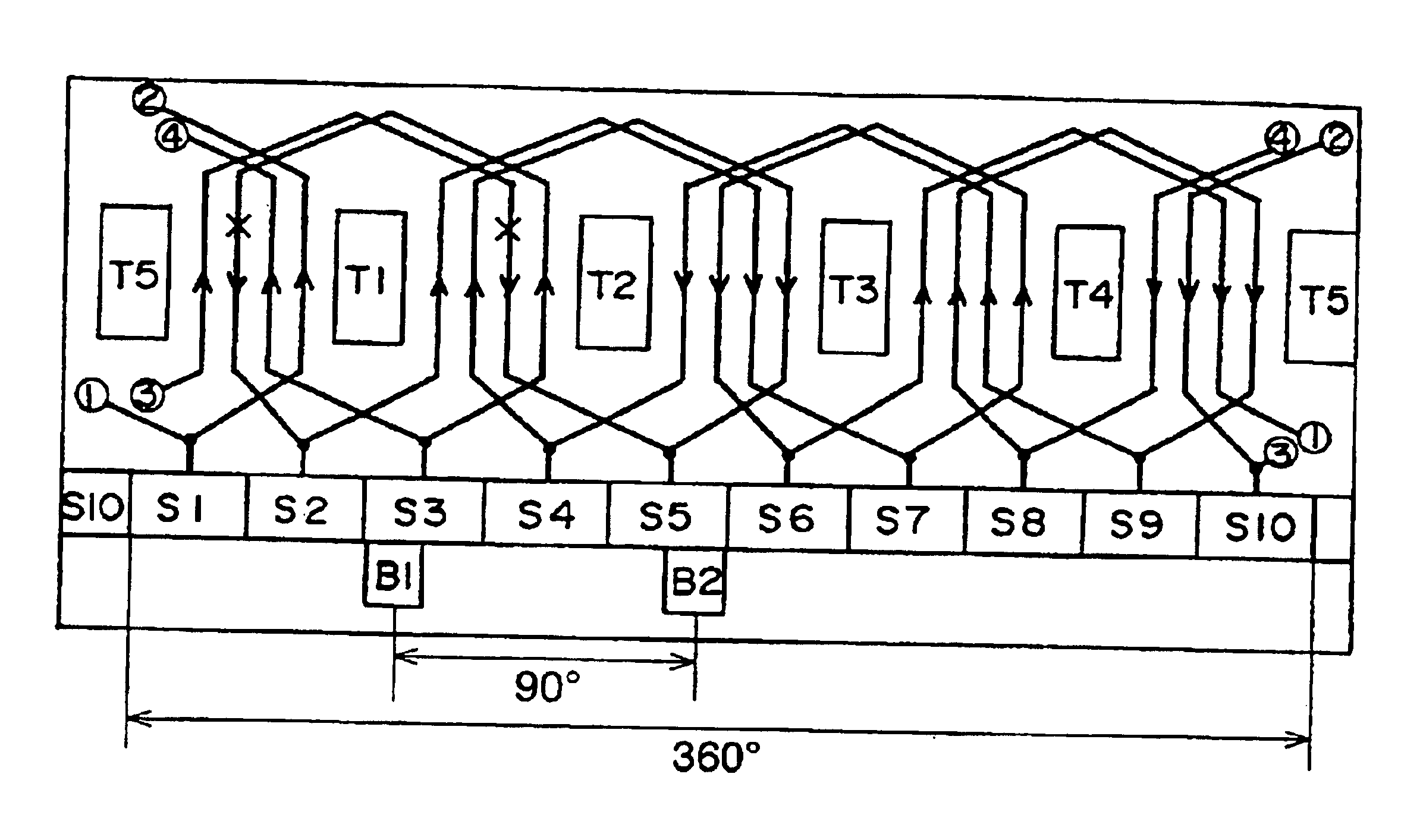
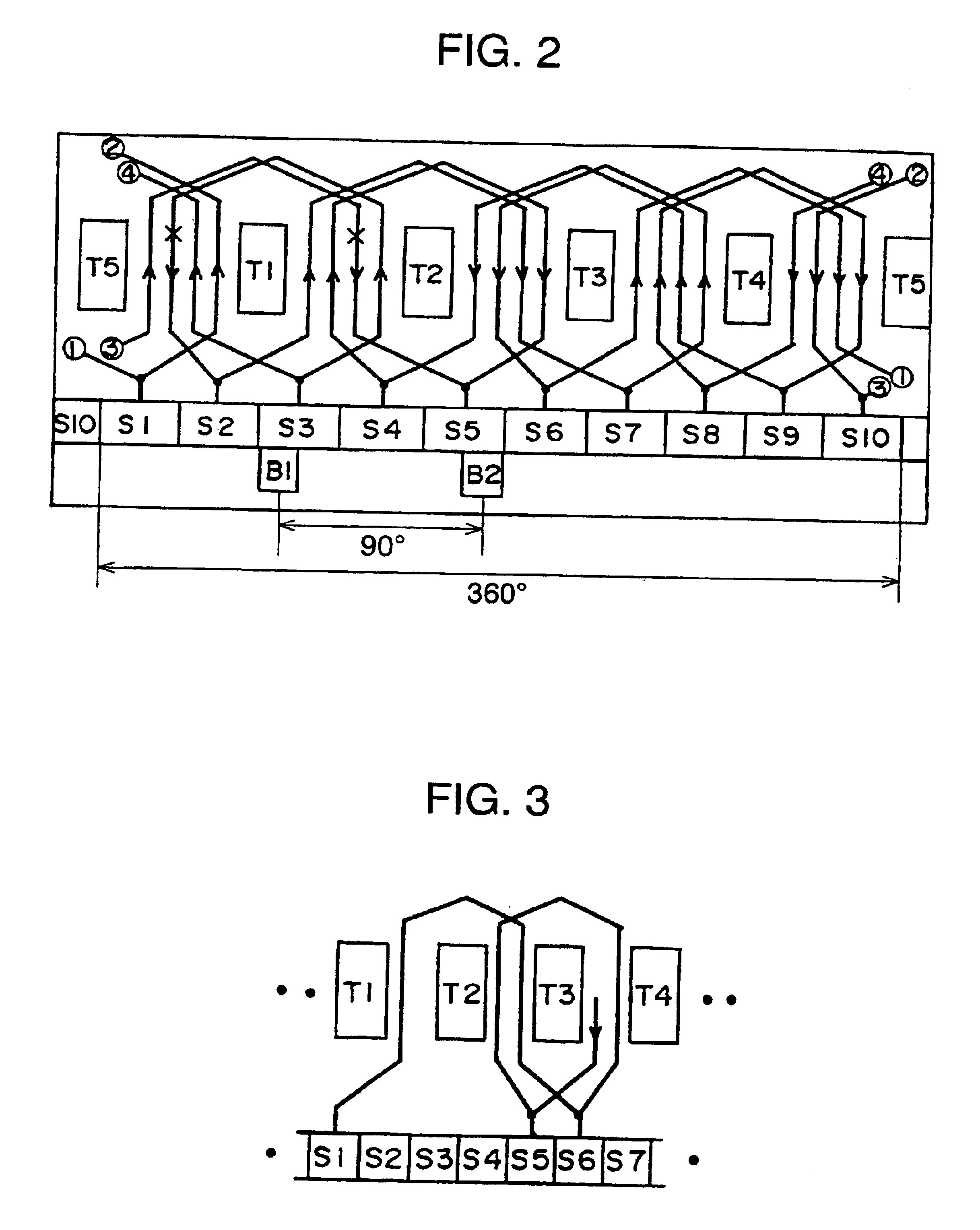
Magnet 37 functioning as a stator is rigidly mounted onto the inner wall of frame 36 of motor 31. Frame 36 houses rotor 35, of which shaft 32 extends through the center of core 44 formed of laminated electromagnetic-steel plates. Rotor 35 is journaled by bearings 33 and 34 at both the ends of shaft 32. Rotor 35 thus faces stator magnet 37 via annular space. Rotor 35 is provided with five slots 40 parallel to the axial line of shaft 32. Five teeth 41 are formed between respective slots 40. Windings (coils) are provided on respective teeth 41. Commutator 42 comprising ten segments is rigidly mounted to one end of rotor 35. Ends of respective coils are coupled to winding connectors 43 linked to respective segments. A pair of brushes contact with commutator 42, so that commutator 42 slides with respect to the pair of bru...
second exemplary embodiment
FIG. 6 is a schematic development of a rotor in accordance with the second exemplary embodiment of the present invention. In this rotor, a dimensional relation between a brush and a commutator of the present invention is employed; however, the conventional winding method still remains. FIG. 9 is a schematic development of windings of a conventional motor, and this winding method is employed in the second embodiment. In FIG. 9, a coil starting from segment S5 is wound on tooth T2, and coupled to segment S6 adjacent to segment S5. The coil extending from segment S6 is wound on tooth T2, then connected to segment S1. This coil connection is applied to all the segments of the rotor shown in FIG. 6, and the dimensional relation between the brush and the commutator in accordance with the second embodiment is applied to this rotor.
In this second embodiment, the conventional winding method shown in FIG. 9 can work with the dimensional relation between the brush and the commutator of the pre...
third exemplary embodiment
FIG. 7 shows a structure of an electric apparatus in accordance with the third exemplary embodiment of the present invention. In FIG. 7, the electric apparatus includes the following elements: (a) housing 51, (b) motor 53 mounted in housing 51; (c) mechanical section 52 driven by motor 53; and (d) a power supply 54 powered via outside power lines 55.
Motor 53 is driven by power supply 54 via lead wires. Rotating torque is transmitted to mechanical section 52 via an output shaft of motor 53, and mechanical section 52 works to load 56. The motor in accordance with the embodiments discussed previously is used as motor 53.
To be more specific, the electric apparatus is, e.g., automotive products mounted to an automobile, or an electric tool. A power window, which electrically opens or closes a car window, is one of good applications. In this case, housing 51 corresponds to a car body or a car door, power supply 54 corresponds to a battery mounted in the car, mechanical section 52 does to ...
PUM
 Abstract
Description
Claims
Application Information
 - R&D
- Intellectual Property
- Life Sciences
- Materials
- Tech Scout
- Unparalleled Data Quality
- Higher Quality Content
- 60% Fewer Hallucinations
Browse by: Latest US Patents, China's latest patents, Technical Efficacy Thesaurus, Application Domain, Technology Topic, Popular Technical Reports.
© 2025 PatSnap. All rights reserved.Legal|Privacy policy|Modern Slavery Act Transparency Statement|Sitemap|About US| Contact US: help@patsnap.com


