Battery charging method

a battery and charging method technology, applied in the field of rechargeable batteries, can solve the problems of inability to modulate the current amplitude based on these two similar voltage situations, inability to achieve the effect of modulating the current amplitude, and inability to achieve the effect of reducing the discharging pulse amplitud

Inactive Publication Date: 2005-01-11
HDM SYST
View PDF13 Cites 59 Cited by
  • Summary
  • Abstract
  • Description
  • Claims
  • Application Information

AI Technical Summary

Benefits of technology

Monitoring voltage of the battery comprises monitoring the quiescent voltage and a voltage immediately following the discharging pulse wherein a post-discharge voltage is defined as the difference between the voltage immediately following the discharging pulse and the quiescent voltage. Maintaining the voltage comprises maintaining the post-discharge voltage at a selected post-discharge voltage level. The selected post-discharge voltage level is approximately 0.2 volt. Adjusting the configuration of the current pulse comprises decreasing the discharging pulse amplitude if the monitored post-discharge voltage is less than the selected post-discharge voltage level. The discharging pulse amplitude is decreased by approximately 0.05 Coulomb / second. Adjusting the configuration of the current pulse comprises increasing the discharging pulse amplitude if the monitored post-discharge voltage is greater than the selected post-discharge voltage level. The discharging pulse amplitude is increased by approximately 0.05 Coulomb / second.
Adjusting the configuration of the current pulse results in change in duty cycle of the charging pulse wherein the duty cycle comprises a ratio between the width of the charging pulse to the period of the cycle. The duty cycle is monitored wherein the duty cycle is a good indicator of state of charge for a wide variety of batteries and wherein the duty cycle is generally independent of the type of battery.

Problems solved by technology

There is a limit, however, on the rate at which the battery can absorb the charge, and such a limit depends on factors such as composition and charge capacity of the battery.
Such a pulse charger has drawbacks, including the charger being rather battery specific.
Thus attempting to modulate the current amplitude based on these two similar voltage situation is not practical at the least, and may be dangerous in certain situations.
The conventional pulse charger suffers from an additional drawback even if the charger is configured for a specific group of batteries.
This practice is disadvantageous, for example, in a charging process where the terminal voltage (during pulsing, relative to the quiescent voltage) decreases near the end of the charging process.
Therefore, a typical conventional pulse charger suffers from reduced charge input as the charge process nears the end.

Method used


Image

  • Battery charging method
  • Battery charging method
  • Battery charging method

Examples


Embodiment Construction

Reference will now be made to the drawings wherein like numerals refer to like parts throughout. The description of methods and their corresponding embodiments of the invention described herein is in context of charging an arbitrary rechargeable battery. In describing the inventive features of the charging process, exemplary values relating to battery parameters are disclosed in context of a standard 12 volt battery. It will be understood, however, that general inventive concepts disclosed herein are equally applicable to any number of rechargeable batteries used in any number of applications (e.g., cellular phone battery charging, standard-sized battery charging, etc.) without departing from the spirit of the invention.

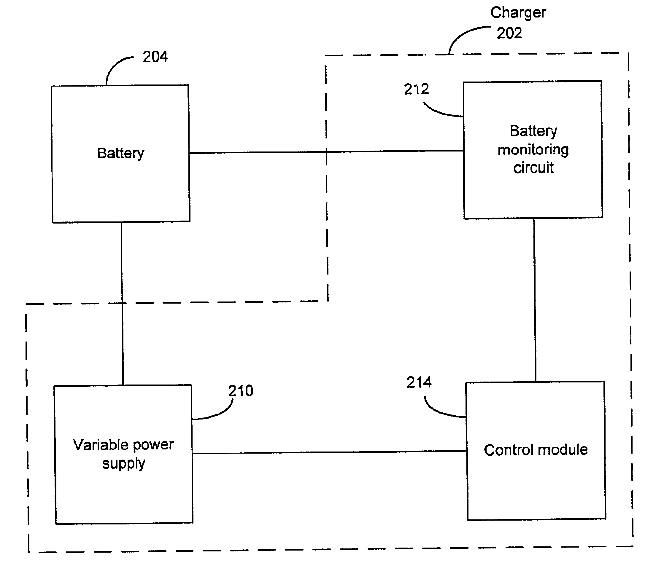
The invention described herein relates to a battery charger that monitors one or more parameters of the battery, and based on the monitored parameters, regulates the charging and or discharging pulses. In particular, the monitored battery parameters include the termi...


PUM


Abstract

A battery charger that adjusts and applies charging pulses to a battery such that one or more battery parameter is regulated. Terminal voltage of the battery, relative to the battery's quiescent voltage, during the charge application is one such battery parameter indicative of the battery's charge absorption rate. Maintaining the charging voltage at a predetermined value during the charging process is achieved by adjusting the charging pulse both amplitude-wise and temporally. The adjustment of the charging pulse is performed such that a high rate of charge input into the battery is maintained during the charging process.

Description

BACKGROUND OF THE INVENTION1. Field of the InventionThe invention relates to rechargeable batteries and, in particular, a battery charging system.2. Description of the Related ArtBatteries are used to power a wide variety of electrical devices. For example, the devices powered by batteries range from a simple flashlight to a complex portable computer. In another example, batteries power devices ranging from a small cellular phone to a relatively large vehicle.A battery is a power source comprising one or more electrochemical cells, also referred to as voltaic cells. Each voltaic cell comprises two electrodes called a cathode and an anode, with an electrolyte therebetween. Electrochemical reaction between the electrolyte and the electrode causes separation of positive and negative charges, wherein the positive charge accumulate on the anode and the negative charge accumulate on the cathode thereby forming a potential difference. When an external path (circuit) is formed between the e...

Claims


Application Information

Patent Timeline
Patent Type & Authority Patents(United States)
IPC IPC(8): H02J7/00
CPCH02J7/0093H02J7/00711
Inventor DYKEMAN, STEVE W.
Owner HDM SYST
Why Eureka
Try Eureka