Electromechanical switching device and emergency shut-off and communication system utilizing same

a technology of electrical switching device and communication system, which is applied in the direction of frequency-division multiplex, testing/monitoring control system, instruments, etc., can solve the problem of increasing the amount of heat generation, large volume of complicated wiring, and inability of assembly b>1/b> to transmit the operation of the operator directly to the target device. problem, to achieve the effect of avoiding the impedance of the communication apparatus, the effect of reducing the impedan

Inactive Publication Date: 2005-01-11
IDEC CORPORATION
View PDF58 Cites 5 Cited by
  • Summary
  • Abstract
  • Description
  • Claims
  • Application Information

AI Technical Summary

Benefits of technology

According to such a configuration, when plural communications apparatuses are collectively arranged, the coils therein are substantially aligned on a line as directing the magnetic fluxes therefrom in the same direction, or the coils are disposed in shifted relation with one another so that the magnetic fluxes from adjoining coils are in the opposite direction. Hence, the magnetic fluxes from the respective coils are prevented from canceling one another so that a decreased impedance of the communications apparatus can be avoided.

Problems solved by technology

However, the aforesaid switch assembly 1 is incapable of transmitting the operation of the operator directly to a target device.
This leads to a disadvantage particularly when the power supply to the apparatus must be shut off in an urgent condition such as emergency stop.
There is a problem that a large volume of complicated wirings is required for the connection of the individual switch assemblies.
This results in an increased amount of heat generation, which leads to a fear of degrading the quality or reliability of the component.
Particularly where the switch sections 21 are collectively disposed, it is difficult to spare an adequate space for heat release and an even greater amount of heat generation results.
Furthermore, the high current value constitutes a drawback of increase in the power consumption.
Unfortunately, a single Zener diode 25 is limited in the ability to accomplish the reduction of the capacity between the transmission terminals INP, INM.
Thus, it has been impossible for a single Zener diode 25 to accomplish a sufficient reduction of the capacity of the transmission path inclusive of the communications contacts 5.
In either case, an increased installation space results.

Method used


Image

  • Electromechanical switching device and emergency shut-off and communication system utilizing same
  • Electromechanical switching device and emergency shut-off and communication system utilizing same
  • Electromechanical switching device and emergency shut-off and communication system utilizing same

Examples


eighth embodiment

(Eighth Embodiment)

A switch assembly according to an eighth embodiment of the present invention will be described with reference to FIGS. 24 to 28. FIG. 24 is a sectional view of the switch assembly; FIG. 25 a sectional view taken on the line A—A in FIG. 24; FIG. 26 a group of explanatory diagrams of an operation of the switch assembly; FIG. 27 a disassembled oblique perspective view of a part of the switch assembly; and FIG. 28 an oblique perspective view of a part of an exemplary modification of the switch assembly. In FIGS. 24 and 25, the same reference characters as those in FIGS. 1 to 23 represent the same or equivalent parts, respectively.

A switch assembly 145 of this embodiment comprises the push-button section 52, the push-button body 53, an adaptor 146 and the communications contact 55. As described in the first embodiment, the push-button section 52 comprises the casing 61, the push button 62 and the operating shaft 63 whereas the push-button body 53 comprises a locking me...

ninth embodiment

(Ninth Embodiment)

A switch assembly according to a ninth embodiment of the present invention will be described with reference to FIG. 29. In FIG. 29, the same reference characters as those in FIGS. 1 to 28 represent the same or equivalent parts, respectively.

A switch assembly 173 of this embodiment comprises the push-button section 52, a push-button body 174, a communication-function incorporating contact (hereinafter referred to as “communications contact”) 175 and a contact-making contact 176.

<Push-Button Body>

The push-button body 174 is formed with a communications-contact dedicated connection groove 178, which is provided with a wiring for establishing electrical connection with the communications contact 175.

<Communications Contact>

The communications contact 175 is provided with a communication circuit within its body and includes a connecting projection 179 for connection with the push-button body 174. The communications contact is formed with a connecting projection...

tenth embodiment

(Tenth Embodiment)

A switch assembly according to a tenth embodiment of the present invention will be described with reference to FIG. 30, which is an oblique perspective view of a part of an internal configuration of a switch assembly 187 of this embodiment. In FIG. 30, the same reference characters as those in FIGS. 1 to 29 represent the same or equivalent parts, respectively.

The switch assembly 187 of this embodiment has a similar arrangement to that of the switch assembly 145 shown in FIG. 24 wherein a pivotal section pivotally mounted on a pivot shaft is pivotally moved by a force from the operating shaft, thereby operating the switch of the contact. However, the assembly of this embodiment is principally different from the switch assembly 145 in that two pairs of operating-shaft dedicated projections 155 and the adaptor dedicated projections 156 formed on the pivotal section are adapted to operate independently from each other.

Such a configuration is particularly advantageous i...


PUM


Abstract

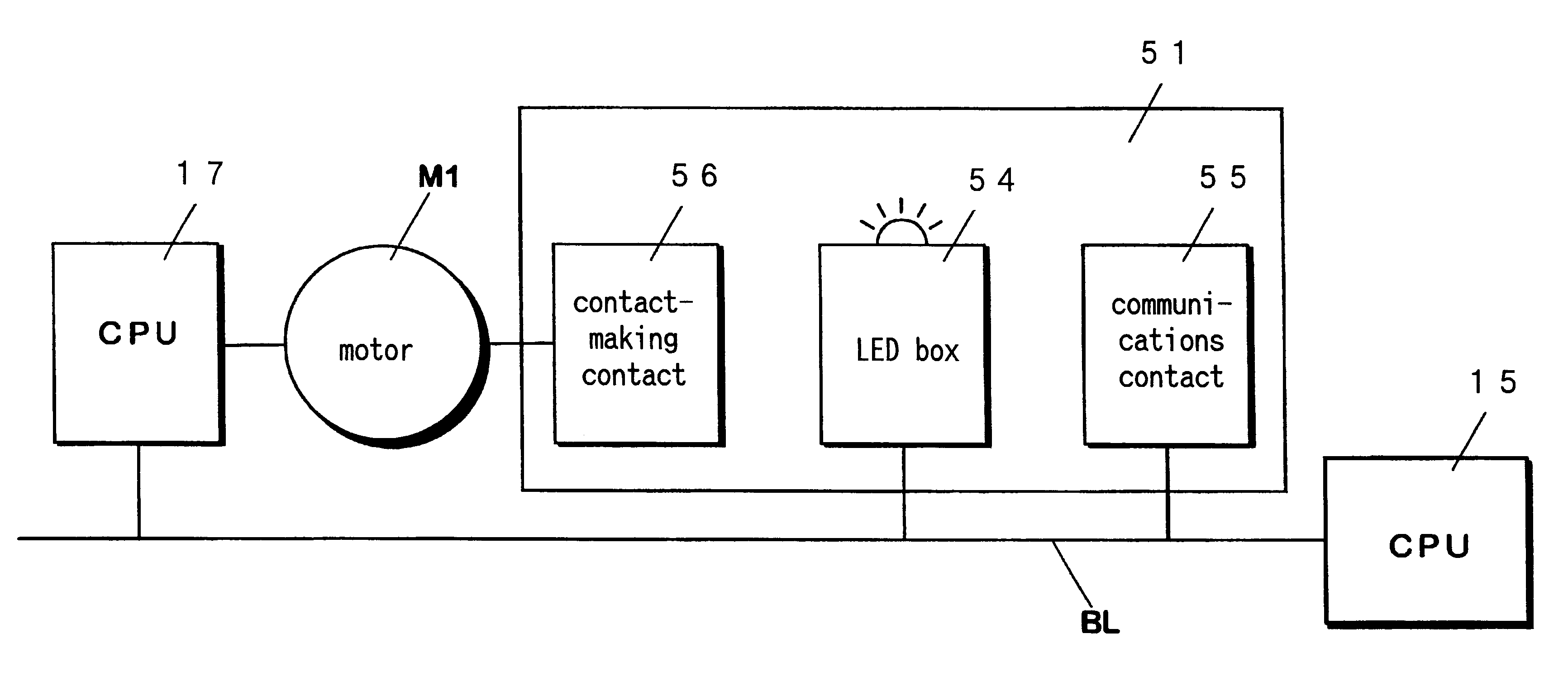
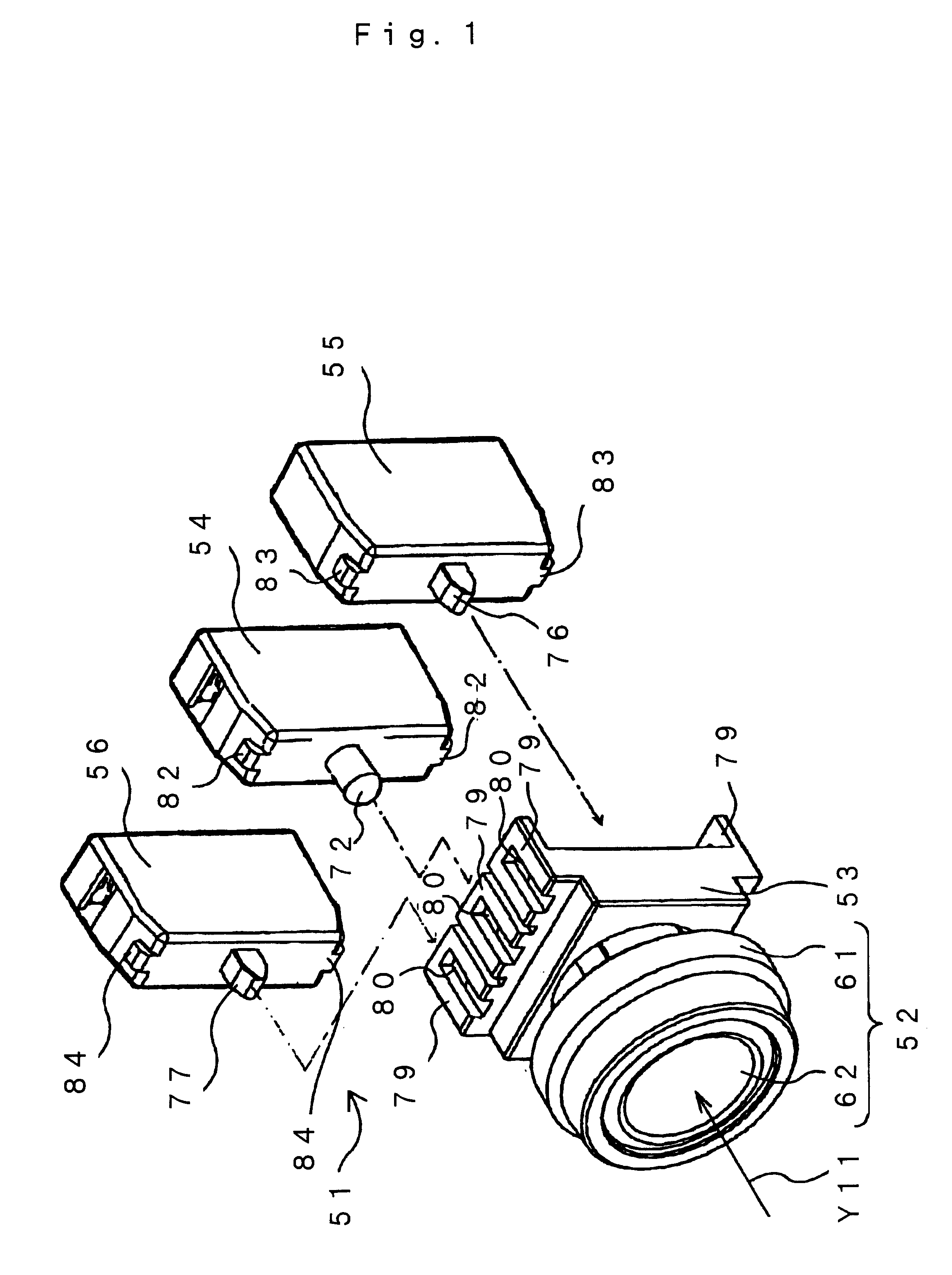
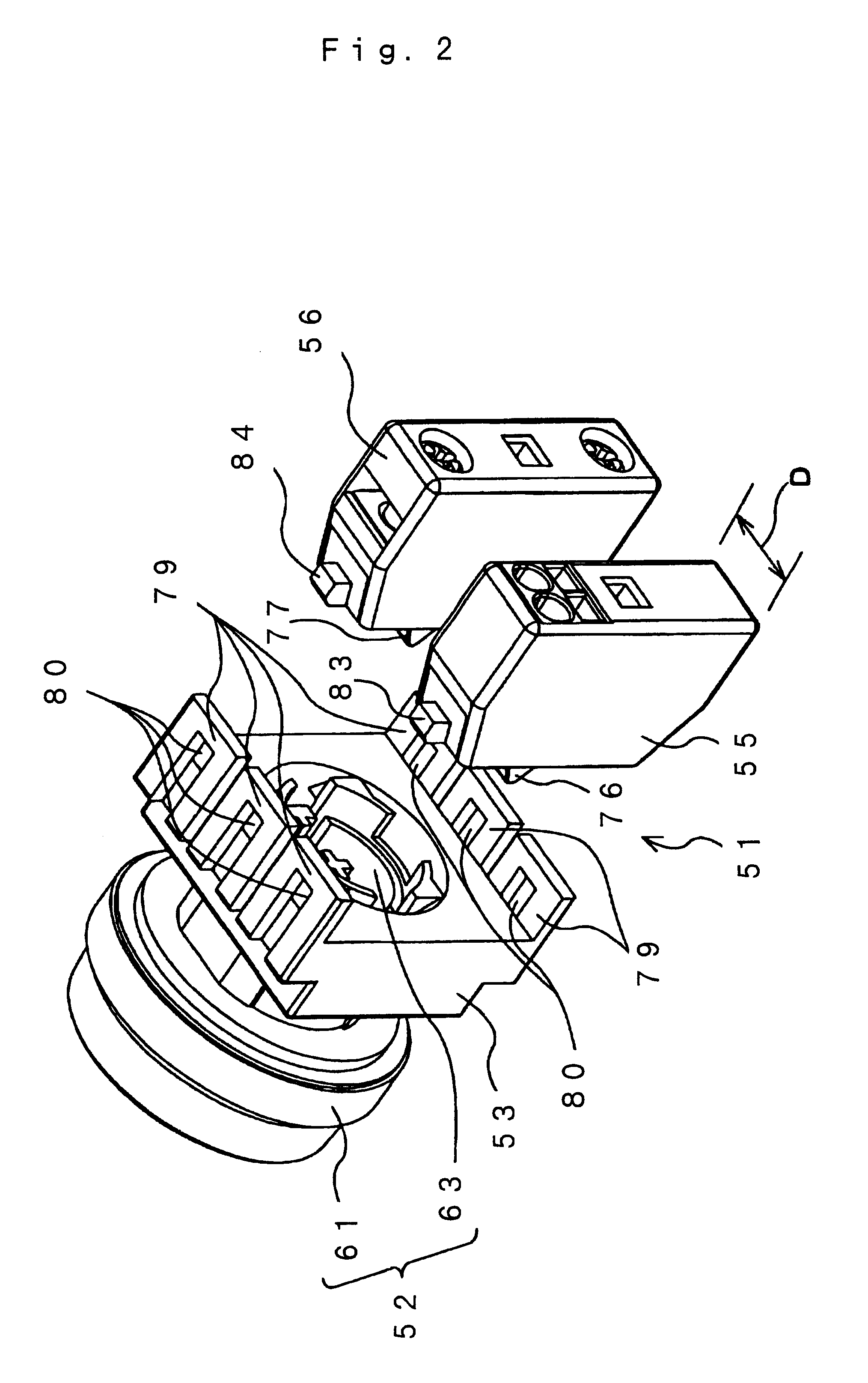
A switch assembly (1) comprises a push-button section (52) and a push-button body (53) as an operation transmitting member, an LED box (54) and a contact-making contact (56) as a direct functioning member, and a communication-function incorporating contact (communications contact) (55) as an information input/output functioning member, as permitting these components to be connected with each other. Therefore, the switch assembly can respond to an operation given to the push-button body (52) by causing the contact-making contact (56) to provide an output for switching between a conductive state and a non-conductive state and by causing the communications contact (55) to output an information signal to a network.

Description

TECHNICAL FIELDThe present invention relates to an electrical component comprising a combination of plural functioning members, as well as to an emergency stop system and a communications apparatus including the same.BACKGROUND ARTThere has been known a switch assembly, such as shown inFIG. 63 for example, as an electrical component for use in a bus-system network and the like which communicates a communication signal composed of a voltage signal by way of two bus lines. A switch assembly 1 comprises a pressing section 2, an operating shaft 3, an adaptor 4 and a communication-function incorporating contact 5.The pressing section 2 accepts an operation given by an operator. The operator can change the state of the contact 5 by depressing the pressing section 2 in a direction of an arrow Y1. At this time, the operating shaft 3 shifts its position in association with the movement of the pressing section 2.On the other hand, the communication-function incorporating contact 5 includes a ...

Claims


Application Information

Patent Timeline
Patent Type & Authority Patents(United States)
IPC IPC(8): H01H13/50H01H13/02H01H13/04H01H3/12H01H9/02H01H13/00H01H13/14
CPCH01H13/023H01H13/503H01H2003/323Y04S20/14H01H2300/03Y02B90/224H01H2229/042Y02B90/20H01H9/00
Inventor FUJITA, TOSHIHIROOKAMOTO, AKITOKITAYAMA, HIDEYUKIOHTA, HIROYUKIMATSUMOTO, ATSUSHIFUJII, MASAAKIYAMANO, MASATAKETABUSE, EITOKUASA, NORIO
Owner IDEC CORPORATION
Why Eureka
Try Eureka