Road monitoring method for a vehicle and a system thereof

a technology for monitoring methods and roads, applied in television systems, distance measurement, instruments, etc., can solve the problems of high cost of mm-wave radar, apt loss of laser radar methods,

Inactive Publication Date: 2005-01-11
HYUNDAI MOTOR CO LTD
View PDF10 Cites 140 Cited by
  • Summary
  • Abstract
  • Description
  • Claims
  • Application Information

AI Technical Summary

Benefits of technology

Alternatively, in said determining whether a road is curved upward or downward, it may be determined that said road is curved upward if a vertical picture-coordinate of a horizon in said picture signal is higher than a predetermined vertical picture-coordinate, and said road is curved downward if a vertical picture-coordinate of a horizon in said picture signal is lower than said predetermined vertical picture-coordinate.

Problems solved by technology

Moreover, the stereo camera method has difficulty in setting of the two cameras, the laser radar method is apt to lose reliability because a laser ray is too narrow and easily scattered by moisture in the air, and the mm-wave radar is very expensive.

Method used


Image

  • Road monitoring method for a vehicle and a system thereof
  • Road monitoring method for a vehicle and a system thereof
  • Road monitoring method for a vehicle and a system thereof

Examples


Embodiment Construction

A preferred embodiment of the present invention will hereinafter be described in detail with reference to the accompanying drawings.

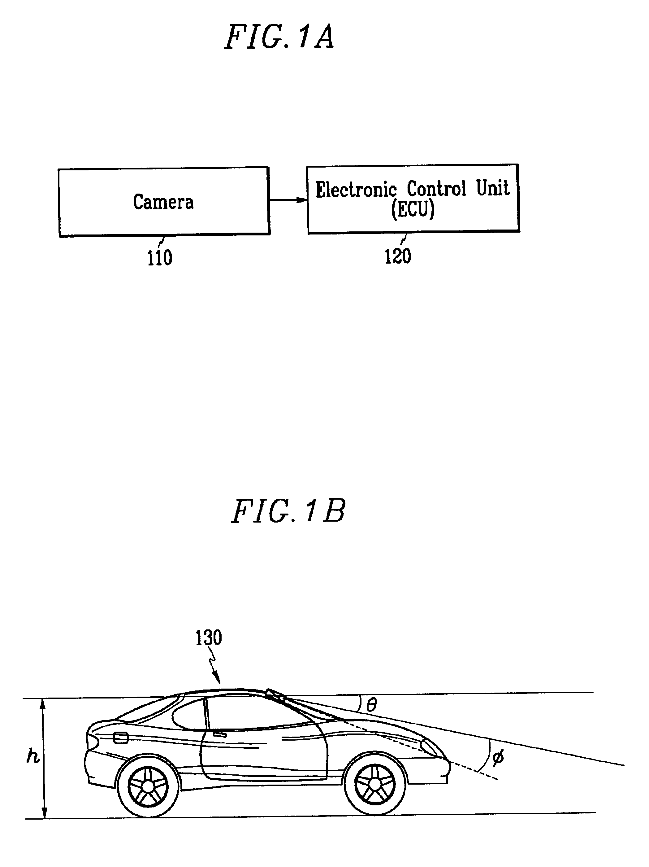
As shown in FIG. 1A, a preferred embodiment of a road monitoring system of the present invention includes a camera 110 generating a picture signal, and an electronic control unit 120 (referred to as “ECU” hereinafter).

The camera 110 is preferably a CCD (Charge Coupled Device) camera such that a captured picture can be easily digitalized to continuously generate picture signals.

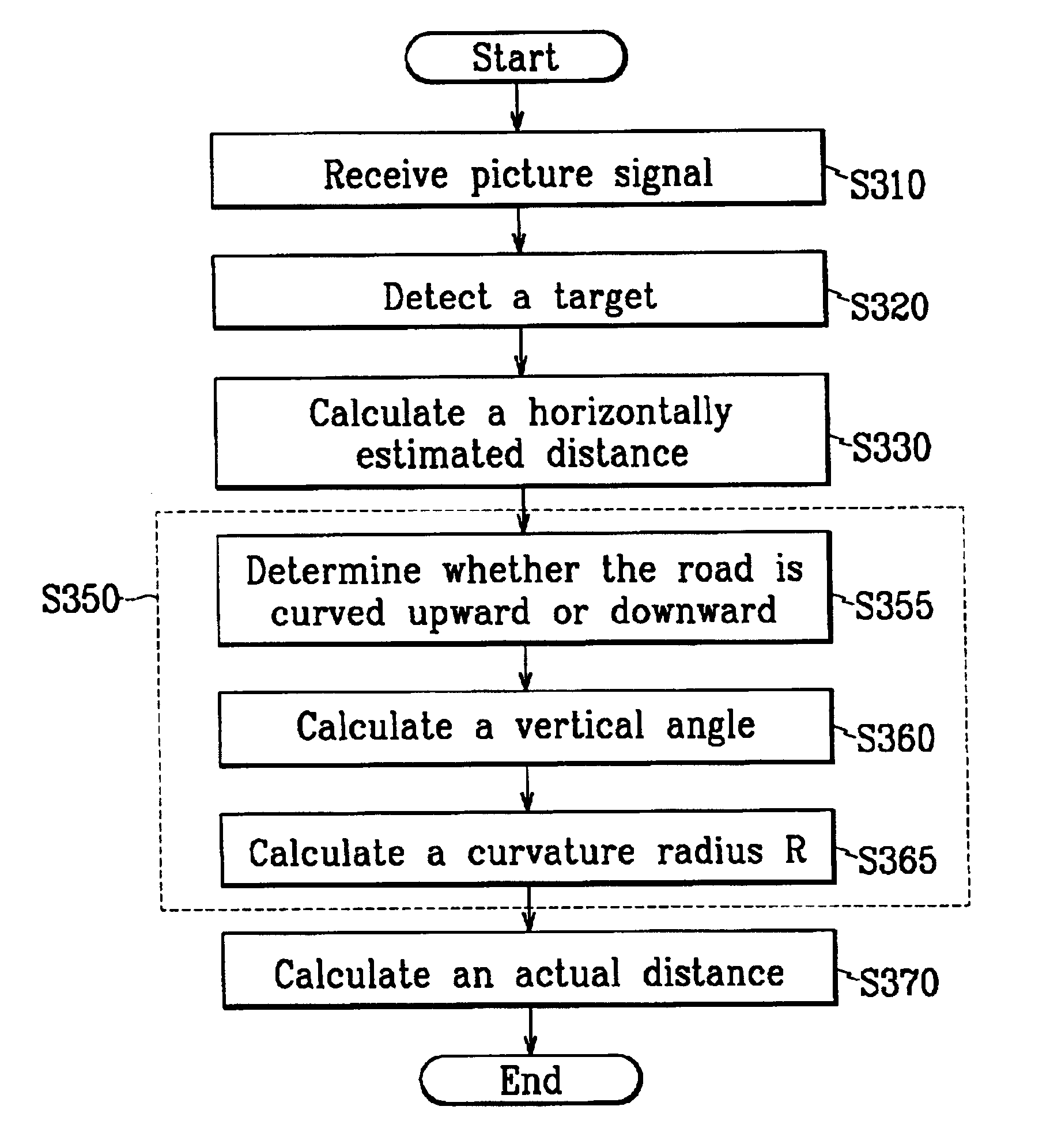
The ECU 120 can be realized by one or more processors activated by predetermined software, and the predetermined software can be programmed to perform each step of a road monitoring method according to a preferred embodiment of this invention.

The ECU 120 can be disposed at any location in a vehicle 130, and the camera 110 is, as shown in FIG. 1B, disposed at an upper front side of the vehicle 130, for example, between a rearview mirror (not shown) and a windshield (not shown).

For ...


PUM


Abstract

In order to measure an actual distance from a vehicle to a target, the target is detected from a picture signal generated by a camera mounted on a vehicle, a horizontally estimated distance of the target is calculated, variables including a vertical angle of the target on a circumference and a curvature radius of the circumference are calculated, and then the actual distance is calculated based on the vertical angle and the curvature radius.

Description

BACKGROUND OF THE INVENTION1. Field of the InventionThe present invention relates to a method and an apparatus for monitoring a road, and more particularly, to a method and an apparatus for monitoring a road wherein road information, such as a distance to a preceding vehicle, is acquired using a picture captured by a camera.2. Description of the Related ArtRecently, an unmanned vehicle, which perceives driving circumstances and automatically controls driving performance, has been under development. Such an unmanned vehicle usually includes a lane marker detector for detecting lane markers to be used for keeping the unmanned vehicle running in the same lane, and a vehicle detector for detecting a preceding vehicle in order to prevent the unmanned vehicle from bumping the preceding vehicle.The lane marker detector detects lane markers from a picture captured by an input apparatus such as a camera, such that the road on which the unmanned vehicle is running can be modeled.Marking objec...

Claims


Application Information

Patent Timeline
Patent Type & Authority Patents(United States)
IPC IPC(8): G01S11/00G01S11/12G01B11/00B60R1/00B60R21/00G06T1/00G06T7/60G08G1/16H04N7/18
CPCG01S11/12G08G1/16
Inventor PARK, KWANG-IL
Owner HYUNDAI MOTOR CO LTD
Why Eureka
Try Eureka