Broad band DUV, VUV long-working distance catadioptric imaging system

a long-working distance, optical system technology, applied in the field of optical imaging, can solve the problems of affecting mechanical stability and manufacturing costs, limited working distance, internal pupil, etc., and achieves the effect of minimizing the central obscuration of the system, long free working distance, and small obscuration

Inactive Publication Date: 2005-01-11
KLA TENCOR TECH CORP
View PDF44 Cites 90 Cited by
  • Summary
  • Abstract
  • Description
  • Claims
  • Application Information

AI Technical Summary

Benefits of technology

In previous systems, the order of the components, proceeding outwards from the high NA image formed by the system, is as follows: catadioptric cavity, intermediate image and field lens, focusing lens group. The present system reverses this previously employed ordering. The high NA image is next to the focusing lens group, then an intermediate image and field lens, then the catadioptric cavity. This reordering of components provides a relatively long free working distance around the high NA image as compared to previous systems.
In the previous component ordering scheme, the working distance is kept very short in order to minimize the central obscuration of the system. Reversing that order provides a long working distance while keeping a very small obscuration, and also retains color correction design aspects and characteristics found in designs using the previous component ordering scheme.

Problems solved by technology

This type of design has several limitations including a limited working distance, central obscuration, internal pupil, and some relatively tight manufacturing tolerances.
This design has a long overall optical path, which in certain circumstances can adversely affect mechanical stability and manufacturing costs.
Also, the optical system has an unusual optical axis near perpendicular that can offer manufacturing challenges.
This design has several limitations including a limited working distance, internal pupil, narrow bandwidth, an internal beamsplitter, and tight manufacturing tolerances.

Method used


Image

  • Broad band DUV, VUV long-working distance catadioptric imaging system
  • Broad band DUV, VUV long-working distance catadioptric imaging system
  • Broad band DUV, VUV long-working distance catadioptric imaging system

Examples


first embodiment

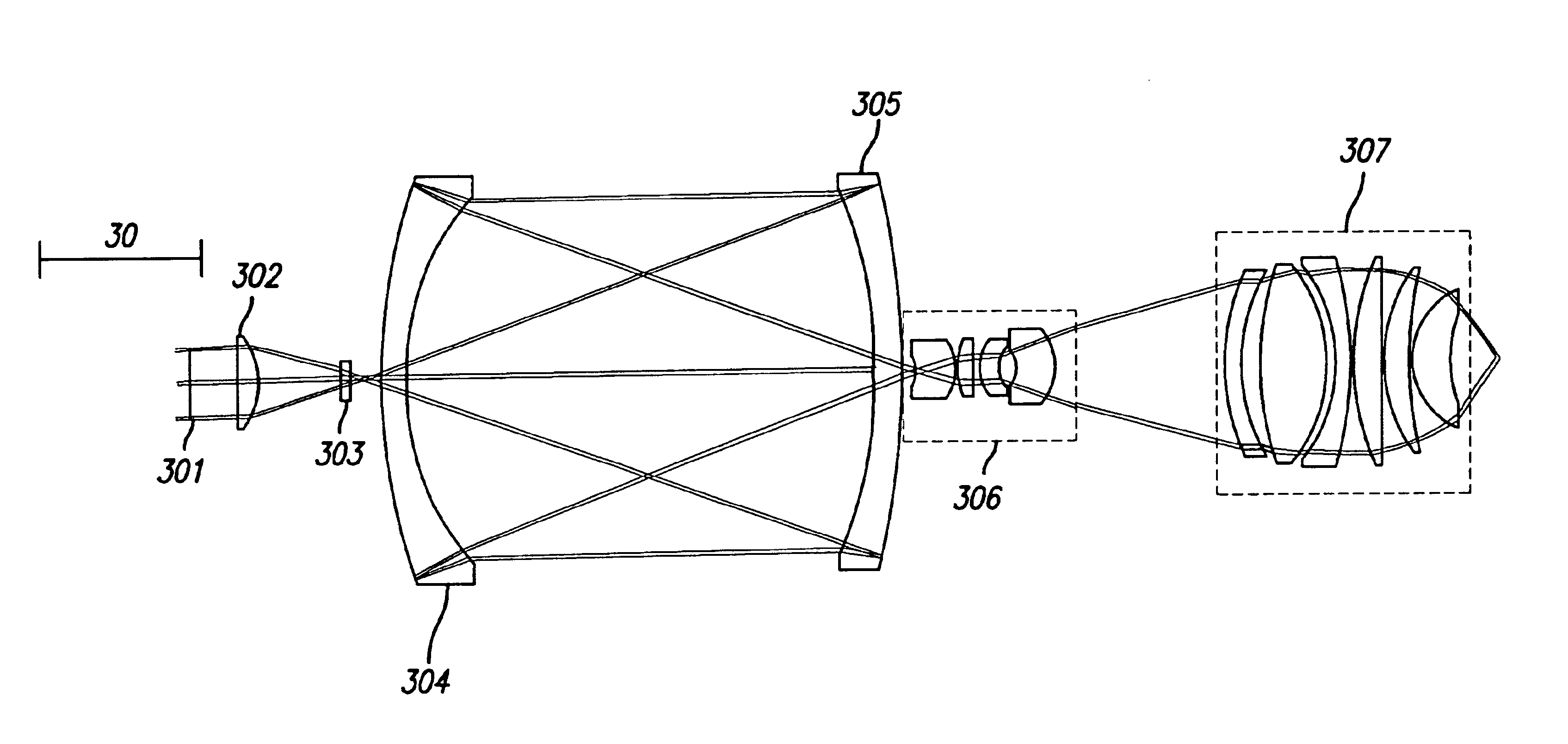
This embodiment has a bandwidth of 1 nm with the central wavelength at 193.30 nm. The numerical aperture is 0.8, while the working distance is greater than 7 millimeters. The central obscuration is less than 5% in diameter at 0.8 NA. Even at 0.35 NA, the central obscuration is still below 16% in diameter, which is equivalent to 2.5% of area obscuration. The surface data for the first embodiment is listed in Table 1.

TABLE 1Surface data of a 193 nm catadioptricdesign with a 1 nm bandwidth as shown in FIG. 4Radius ofSurface #curvatureThicknessGlassOBJInfinityInfinityAirSTOInfinity15.188841Air 2−81.6279083.5Silica 3−18.04068522.449116Air 418.744572Silica 5795.1375921.998104Air 684.9966625Silica 740.30242297.532362Air 8−78.5674765Silica 9−132.110046−5Reflector / Silica10−78.567476−97.532362Air1140.302422−5Silica1284.9966625Reflector / Silica1340.30242297.532362Air14−78.5674765Silica15−132.11004614.180612Air1641.9060432.999944Silica17−19.6453290.499948Air1810.2065346.643053Silica196.3142745.3...


PUM

PropertyMeasurementUnit
center wavelengthaaaaaaaaaa
wavelengthsaaaaaaaaaa

Abstract

A high performance objective having very small central obscuration, an external pupil for apertureing and Fourier filtering, loose manufacturing tolerances, large numerical aperture, long working distance, and a large field of view is presented. The objective is preferably telecentric. The design is ideally suited for both broad-band bright-field and laser dark field imaging and inspection at wavelengths in the UV to VUV spectral range.

Description

BACKGROUND OF THE INVENTION1. Field of the InventionThe present invention relates generally to the field of optical imaging and more particularly to catadioptric optical systems used for microscopic imaging, inspection, and lithography applications.2. Description of the Related ArtMany optical and electronic systems exist to inspect surface features for defects such as those on a partially fabricated integrated circuit or a photomask. Defects may take the form of particles randomly localized on the surface, scratches, process variations, and so forth. Such techniques and devices are well known in the art and are embodied in various commercial products such as many of those available from KLA-Tencor Corporation of San Jose, Calif., the assignee of the present application.Specialized optical systems are required to enable the imaging and inspection of surface defects, such as those found on semiconductor wafers and photomasks. Two prior inventions describe high numerical aperture (NA)...

Claims


Application Information

Patent Timeline
Patent Type & Authority Patents(United States)
IPC IPC(8): G02B21/04G02B21/02G02B17/08G03F7/20
CPCG02B13/143G02B17/0804G02B17/0808G03F7/70225G02B17/0892G02B21/04G02B17/0856
Inventor SHAFER, DAVID R.CHUANG, YUNG-HO
Owner KLA TENCOR TECH CORP
Why Eureka
Try Eureka