Broad band DUV, VUV long-working distance catadioptric imaging system

a long-working distance, optical system technology, applied in the field of optical imaging, can solve the problems of affecting mechanical stability and manufacturing costs, limited working distance, internal pupil, etc., and achieves the effect of minimizing the central obscuration of the system, long free working distance, and small obscuration

Inactive Publication Date: 2006-11-14
KLA TENCOR TECH CORP
View PDF45 Cites 20 Cited by
  • Summary
  • Abstract
  • Description
  • Claims
  • Application Information

AI Technical Summary

Benefits of technology

[0018]In previous systems, the order of the components, proceeding outwards from the high NA image formed by the system, is as follows: catadioptric cavity, intermediate image and field lens, focusing lens group. The present system reverses this previously employed ordering. The high NA image is next to the focusing lens group, then an intermediate image and field lens, then the catadioptric cavity. This reordering of components provides a relatively long free working distance around the high NA image as compared to previous systems.
[0019]In the previous component ordering scheme, the working distance is kept very short in order to minimize the central obscuration of the system. Reversing that order provides a long working distance while keeping a very small obscuration, and also retains color correction design aspects and characteristics found in designs using the previous component ordering scheme.
[0020]In addition to color correction, the present invention also includes an objective that can be used as microscope or as micro-lithography optics with a large numerical aperture, long working distance, and a large field of view. The objective is preferably telecentric and is a high performance objective with very small central obscuration, an external pupil for apertureing and Fourier filtering, and relatively loose manufacturing tolerances. The present invention is suited to both broad-band bright-field and laser dark field imaging and inspection at wavelengths below 350 nm.

Problems solved by technology

This type of design has several limitations including a limited working distance, central obscuration, internal pupil, and some relatively tight manufacturing tolerances.
This design has a long overall optical path, which in certain circumstances can adversely affect mechanical stability and manufacturing costs.
Also, the optical system has an unusual optical axis near perpendicular that can offer manufacturing challenges.
This design has several limitations including a limited working distance, internal pupil, narrow bandwidth, an internal beamsplitter, and tight manufacturing tolerances.

Method used


Image

  • Broad band DUV, VUV long-working distance catadioptric imaging system
  • Broad band DUV, VUV long-working distance catadioptric imaging system
  • Broad band DUV, VUV long-working distance catadioptric imaging system

Examples


first embodiment

[0040]This embodiment has a bandwidth of 1 nm with the central wavelength at 193.30 nm. The numerical aperture is 0.8, while the working distance is greater than 7 millimeters. The central obscuration is less than 5% in diameter at 0.8 NA. Even at 0.35 NA, the central obscuration is still below 16% in diameter, which is equivalent to 2.5% of area obscuration. The surface data for the first embodiment is listed in Table 1.

[0041]

TABLE 1Surface data of a 193 nm catadioptricdesign with a 1 nm bandwidth as shown in FIG. 4Radius ofSurface #curvatureThicknessGlassOBJInfinityInfinityAirSTOInfinity15.188841Air2−81.6279083.5Silica3−18.04068522.449116Air418.744572Silica5795.1375921.998104Air684.9966625Silica740.30242297.532362Air8−78.5674765Silica9−132.110046−5Reflector / Silica10−78.567476−97.532362Air1140.302422−5Silica1284.9966625Reflector / Silica1340.30242297.532362Air14−78.5674765Silica15−132.11004614.180612Air1641.9060432.999944Silica17−19.6453290.499948Air1810.2065346.643053Silica196.31427...

second embodiment

[0051]the current invention is shown in FIG. 5. The design of FIG. 5 is a more complex version of the 193 nm optical design with emphasis on loose tolerances. From FIG. 5, light energy passes pupil plane 501 to first lens 502 and field lens group 503 to mangin mirror 504 and lens 505. Light energy reflects between the mangin mirror 504 and mangin mirror 506 before leaving through the hole in mangin mirror 506. Light then passes through field lens group 507, including first through fourth field lenses 507a through 507d, and focussing lens group 508, including first through sixth focusing lenses 508a through 508f.

[0052]One major difference between the design of FIG. 4 and that of FIG. 5 is the addition of a lens 505 inside the catadioptric cavity. The extra lens 505 enables simple modification of higher-order aberrations and results in diminished requirements for the field lens group 507. The resulting field lens group 507 exhibits decreased tolerance sensitivity compared with previo...

third embodiment

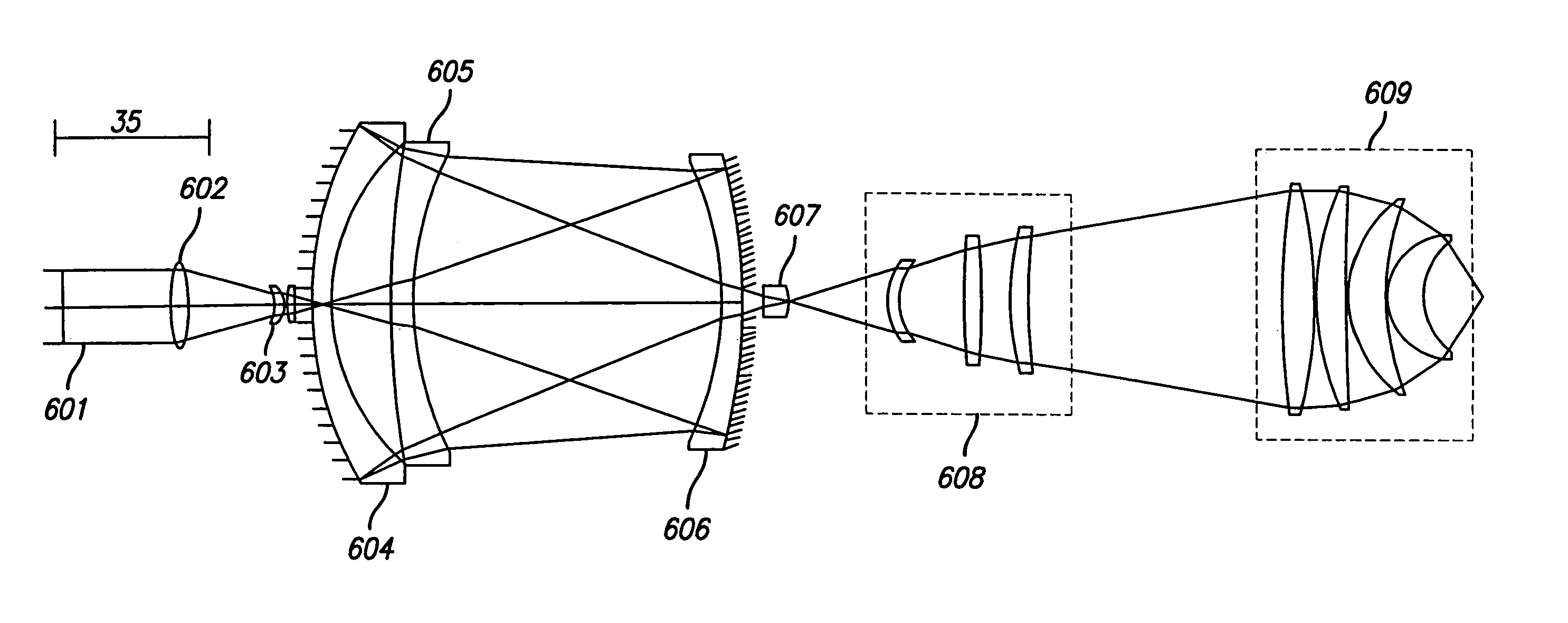
[0055]the present invention is a 0.85 NA design for 157 nm and is shown in FIG. 6. From FIG. 6, pupil plane 601 is to the left of first lens 602 and field lens group 603. Light energy passing through first lens 602 and field lens group 603 is directed to mangin mirror 604, lens 605, mangin mirror 606, lens 607, field lens group 608, and focussing lens group 609. Field lens group 608 comprises first through third lenses 608a through 608c and focussing lens group 609 comprises first through sixth lenses 609a through 609f.

[0056]The field sizes for the 0.85 NA and the 0.386 NA modes of operation are 0.264 mm diameter and 0.58 mm diameter, respectively. A + / −5 microns decenter of any element leaves the on-axis Strehl value above 0.80, and the arrangement shown in FIG. 6 has been optimized for this decentering. Addition of compensation elements provides for variances in manufacturing tolerances without appreciable degradation. The surface data for one example of the type of design presen...


PUM


Abstract

A high performance objective having very small central obscuration, an external pupil for apertureing and Fourier filtering, loose manufacturing tolerances, large numerical aperture, long working distance, and a large field of view is presented. The objective is preferably telecentric. The design is ideally suited for both broad-band bright-field and laser dark field imaging and inspection at wavelengths in the UV to VUV spectral range.

Description

[0001]This application is a continuation of U.S. patent application Ser. No. 09 / 796,117, entitled “Broad Band DUV, VUV Long-Working Distance Catadioptric Imaging System,” filed on Feb. 28, 2001, now U.S. Pat. No. 6,842,298, which claims the benefit of U.S. Provisional Patent Application 60 / 231,761, entitled “Broad Band DUV, VUV Long-Working Distance Catadioptric Imaging System,” filed on Sep. 12, 2000, both of which are hereby incorporated by reference.BACKGROUND OF THE INVENTION[0002]1. Field of the Invention[0003]The present invention relates generally to the field of optical imaging and more particularly to catadioptric optical systems used for microscopic imaging, inspection, and lithography applications.[0004]2. Description of the Related Art[0005]Many optical and electronic systems exist to inspect surface features for defects such as those on a partially fabricated integrated circuit or a photomask. Defects may take the form of particles randomly localized on the surface, scr...

Claims


Application Information

Patent Timeline
Patent Type & Authority Patents(United States)
IPC IPC(8): G02B21/10G02B17/00G02B21/12G02B13/14G02B13/22G02B17/08
CPCG02B13/143G02B13/22G02B17/0808G02B17/086G02B17/0892
Inventor SHAFER, DAVID R.CHUANG, YUNG-HO
Owner KLA TENCOR TECH CORP
Why Eureka
Try Eureka