Method for modelling fluid flows in a fractured multilayer porous medium and correlative interactions in a production well

a multi-layer porous medium and fluid flow technology, applied in seismology for waterlogging, borehole/well accessories, instruments, etc., can solve the problems of difficult meshing of spaces, large number of meshes to be processed, and difficult implementation, so as to simplify the calculation of exchanges

Inactive Publication Date: 2005-01-11
INST FR DU PETROLE
View PDF6 Cites 82 Cited by
  • Summary
  • Abstract
  • Description
  • Claims
  • Application Information

AI Technical Summary

Benefits of technology

The method according to the invention greatly simplifies calculation of the exchanges between the matrix and the fractures. In fact, there is no specific mesh pattern for the matrix, but each node of the fracture network is associated with a matrix volume, and the flow between each fracture node and its associated block is calculated in a pseudosteady state. The invention concerns calculation of the volume of each block and of a proportionality coefficient (called transmissivity) that connects the matrix-fracture flow rate to the matrix-fracture pressure difference.
The main advantage of the method according to the invention in relation to methods applied to a finely meshed real fracture network lies, as detailed in the description hereafter, in a considerable reduction in a number of meshes centered on fracture nodes used to solve equation (1). The simulation rate saving in relation to prior fine-mesh methods can be confirmed to be greater than the simple arithmetical ratio of the number of meshes used in both cases.

Problems solved by technology

However, these tools are not applied to the real geologic medium in view of the complexity thereof and instead are applied to a homogenized representation, according to the reservoir model called a “double-medium model” described for example by Warren and Root in “The Behavior of Naturally Fractured Reservoirs”, SPE Journal, September 1963.
It is however difficult to implement because the often complex geometry of the spaces between the fractures makes difficult the meshing of the spaces.
In any case, the number of meshes to be processed is often very large.
The complexity increases still further with a 3D mesh pattern.

Method used


Image

  • Method for modelling fluid flows in a fractured multilayer porous medium and correlative interactions in a production well
  • Method for modelling fluid flows in a fractured multilayer porous medium and correlative interactions in a production well
  • Method for modelling fluid flows in a fractured multilayer porous medium and correlative interactions in a production well

Examples


Embodiment Construction

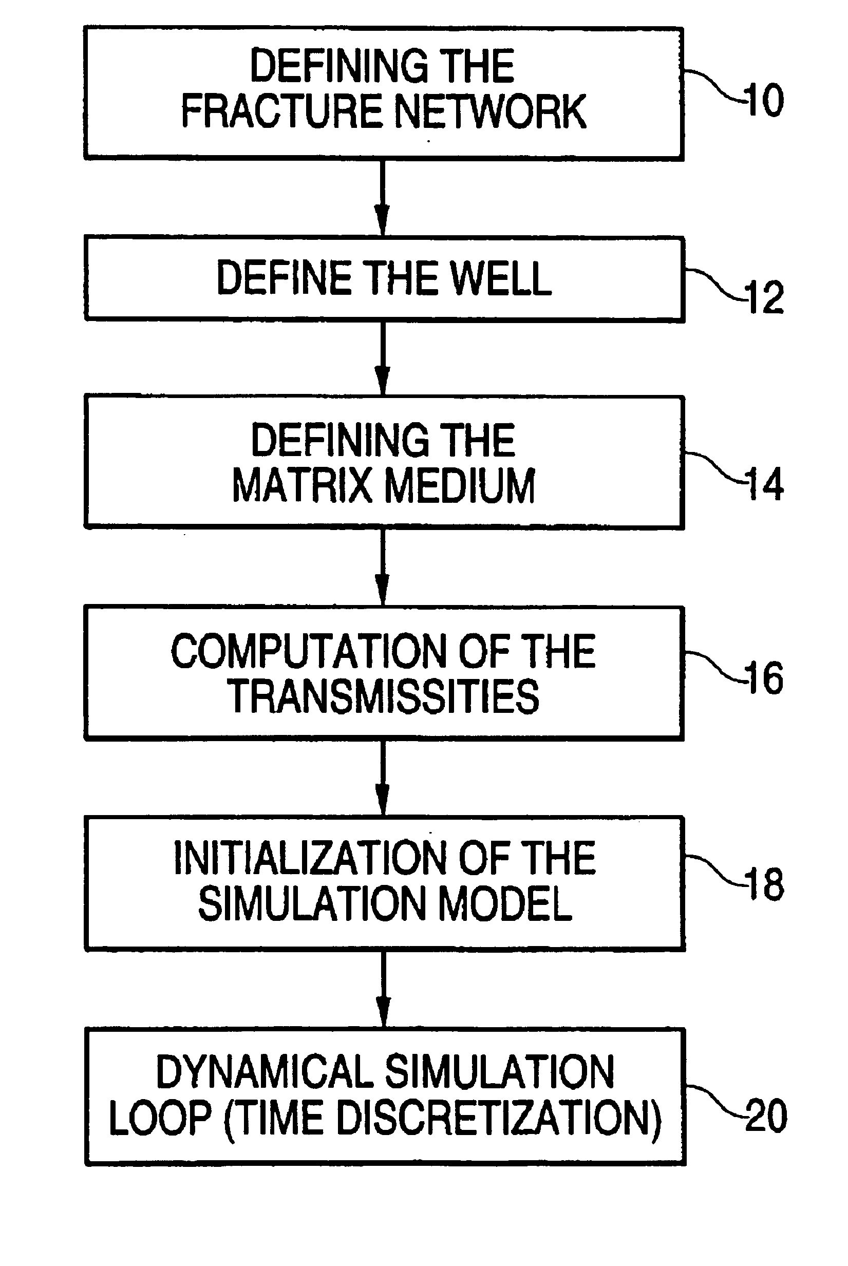
1) Fracture network discretization

The method comprises meshing the multilayer fractured reservoir modelled for example by means of the fractured reservoir modelling technique described notably in the aforementioned French Patent 2,757,947 assuming that the fractures are substantially perpendicular to the layer boundaries.

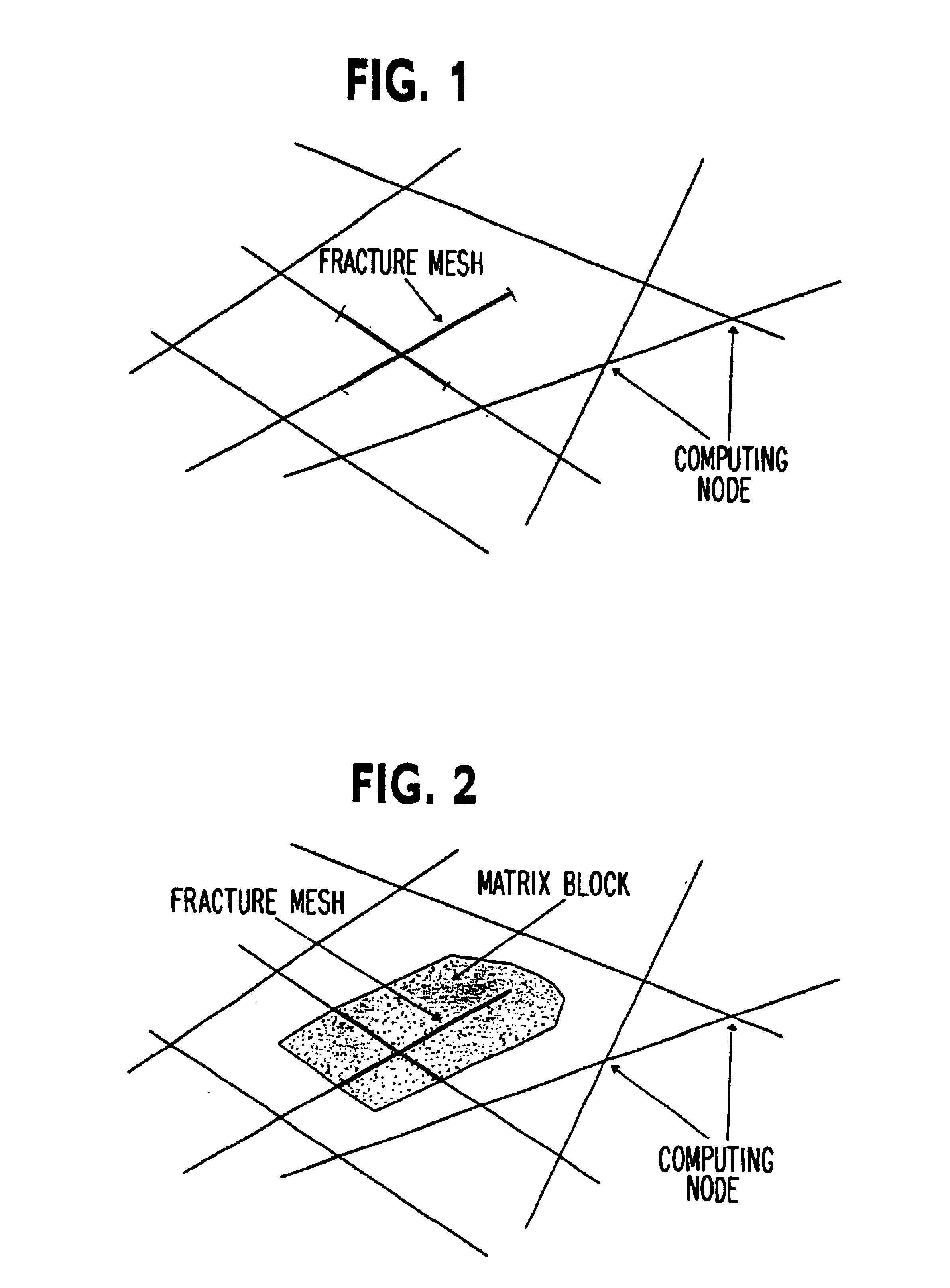
In order to form this mesh pattern, all the fracture intersections or computing nodes are located (FIG. 1) and fracture meshes are formed by associating a single matrix block MB (FIG. 2) with each node. For the purpose of 3D modelling, additional nodes have to be added in the neighboring layers in order to account for the fractures that run across several layers. The computed nodes thus defined constitute the center of the fracture meshes. The meshes are given boundaries such as the ends of the fractures on the one hand and the midpoint of the segments connecting the computing nodes on the other hand. Considering these boundaries imposed on the meshes, the volume φ ...


PUM


Abstract

A method is disclosed for modelling fluid flows in a fractured multilayer porous medium by accounting for the real geometry of the fracture network and the local exchanges between the porous matrix and the fractures at each node of the network, thus allowing simulation of the interactions between the pressure and flow rate variations in a well running across the medium. The method essentially comprises discretizing the fractured medium by means of a mesh pattern, with fracture meshes centered on nodes at the various intersections of the fractures with each node being associated with a matrix volume, and determination of the flows between each fracture mesh and the associated matrix volume in a pseudosteady state. The method can be applied in hydrocarbon production well testing.

Description

BACKGROUND OF THE INVENTION1. Field of the InventionThe present invention relates to a method for simulating well tests on a discrete fractured reservoir model.2. Description of the Prior ArtSingle-phase flow computing tools are currently used. However, these tools are not applied to the real geologic medium in view of the complexity thereof and instead are applied to a homogenized representation, according to the reservoir model called a “double-medium model” described for example by Warren and Root in “The Behavior of Naturally Fractured Reservoirs”, SPE Journal, September 1963. Any elementary volume of the fractured reservoir is thus modelled in the form of a set of identical parallelepipedic blocks limited by an orthogonal system of continuous uniform fractures oriented in the direction of one of the three main directions of flow (model referred to as “sugar box” model). The fluid flow on the reservoir scale occurs through the fractured medium only, and fluid exchanges take plac...

Claims


Application Information

Patent Timeline
Patent Type & Authority Patents(United States)
IPC IPC(8): E21B49/00G01V11/00
CPCG01V11/00E21B49/00
Inventor SARDA, SYLVAIN
Owner INST FR DU PETROLE
Why Eureka
Try Eureka