Programmable chaos generator and process for use thereof

Inactive Publication Date: 2005-01-11
STMICROELECTRONICS SRL
View PDF5 Cites 35 Cited by
  • Summary
  • Abstract
  • Description
  • Claims
  • Application Information

AI Technical Summary

Problems solved by technology

However, all transmission channels have to deal with some sort of disturbance.
In addition, an important source of disturbance is represented by the possible presence of various transmitters operating in the same environment.
The various sources of information thus available are often indistinguishable by the receiver, thus giving rise to problems of mismatching which frequently go well beyond normal problems of interference.
In this way, a larger number of symbols than what would stric

Method used


Image

  • Programmable chaos generator and process for use thereof
  • Programmable chaos generator and process for use thereof
  • Programmable chaos generator and process for use thereof

Examples


Embodiment Construction

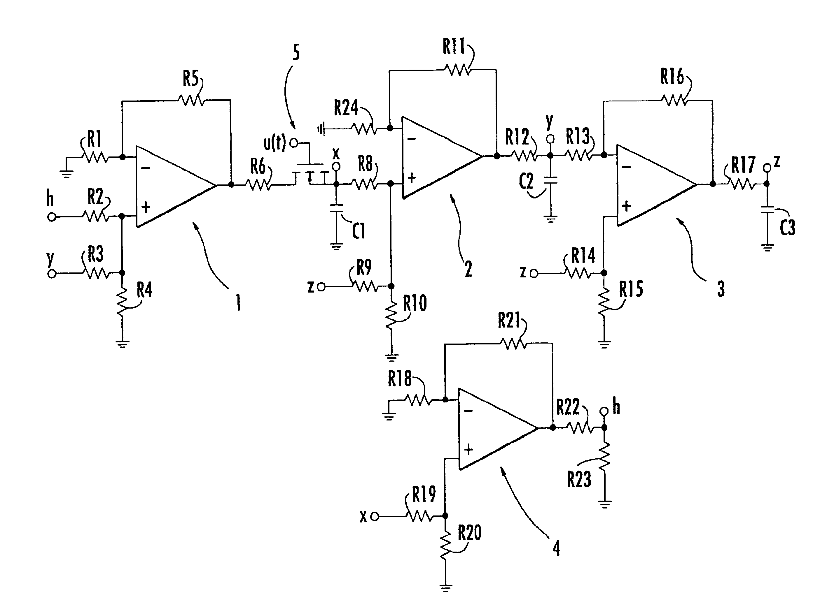
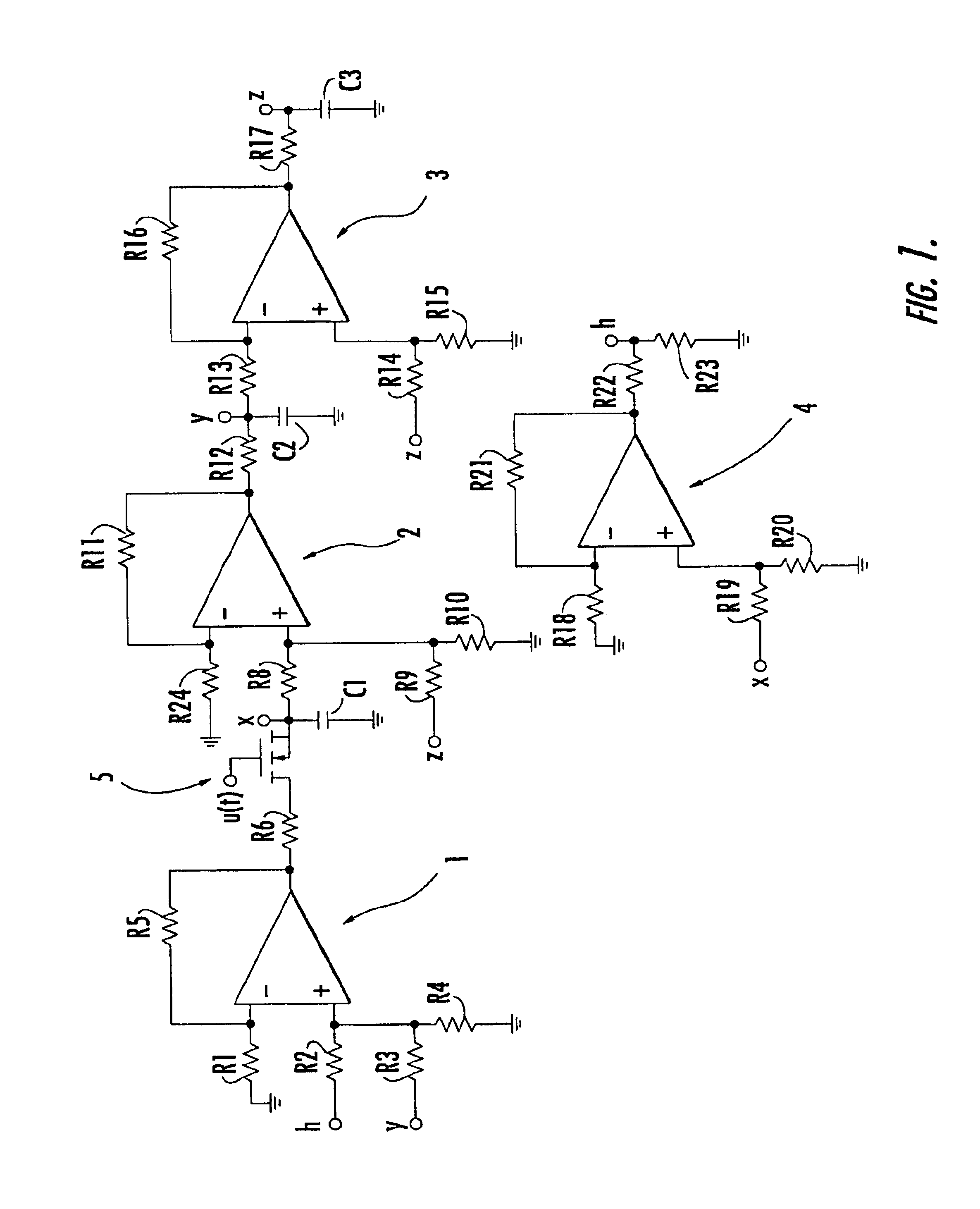
FIG. 1 is a diagram of one embodiment of the circuit for generating chaotic signals. This scheme is known as Chua's circuit. In particular, the diagram of FIG. 1 shows how this previously known approach may be modified to implement the invention. The circuit is illustrated as a state controlled cellular neural network (SC-CNN), as is described, for example, in the work by Manganaro et al. referred to previously.

Chua's circuit represented in FIG. 1 is made up of essentially four cells designated by 1, 2, 3 and 4. In particular, the cells 1 to 3 may be viewed as three cascaded cells, with the output signal of one cell supplying the input of the next cell. The cell 4 may instead be viewed as a feedback element. In this regard, note the connections with the cell 1 and the cell 2, designated by h and x, respectively.

The core of each of the cells 1 to 4 includes a differential amplifier (e.g., an operational amplifier) with negative feedback between the output and the negative input. The ...


PUM


Abstract

A chaotic signal generator includes a set of elements connected together for generating chaotic signals. The connection scheme may correspond to the circuit generally referred to as Chua's circuit, particularly when implemented as a cellular neural network. Interposed in the connection scheme is at least one switch, such as a MOS transistor. Opening and closing of the switch causes variation in the chaotic dynamics of the generated signals. A command signal applied to the switch may correspond to a modulating signal for transmission on a channel, such as a high noise channel. The modulating signal may be a binary signal, and the command signal may be a switching signal having a frequency that increases or decreases depending on the logic level of the binary signal.

Description

FIELD OF THE INVENTIONThe present invention relates to signal generators, and more particularly, to a signal generator having chaotic dynamics that may be used for communications in noisy environments.BACKGROUND OF THE INVENTIONModern communication systems, and in particular, telecommunication systems, are usually classified according to factors such as the nature of the signal (digital or analog) used by the systems, the type of transmission, the transmission medium, the type of channel, and the nature of the receiver.The basic objective of any communication system is to ensure that the information entered on the transmission channel is received correctly or, better still, efficiently. The purpose is to obtain, at the receiver, information that is as close as possible to the information transmitted.If an ideal transmission channel were available, no particular measures would have to be taken to achieve the abovementioned result. However, all transmission channels have to deal with ...

Claims


Application Information

Patent Timeline
IPC IPC(8): H04L27/00
CPCH04L27/001
Inventor OCCHIPINTI, LUIGIFORTUNA, LUIGIRIZZO, ALESSANDROFRASCA, MATTIA
Owner STMICROELECTRONICS SRL
Why Eureka
Try Eureka