
Gas turbine with flexible combustion sensor connection

a flexible combustion and sensor technology, applied in the direction of engines, mechanical equipment, machines/engines, etc., can solve the problems of high stress and easy mechanical damage of the wire connection, and achieve the effect of avoiding excessively strict mechanical alignment criteria and facilitating maintenance of the sensor and engine components

Inactive Publication Date: 2005-01-18
SIEMENS ENERGY INC
View PDF17 Cites 22 Cited by
  • Summary
  • Abstract
  • Description
  • Claims
  • Application Information

AI Technical Summary

Benefits of technology

An improved arrangement for mounting a combustion chamber sensor on a gas turbine engine is desired. Such arrangement should provide protection for the sensor and pressure boundary components, should facilitate maintenance of the sensor and engine components, and should avoid excessively strict mechanical alignment criteria.

Problems solved by technology

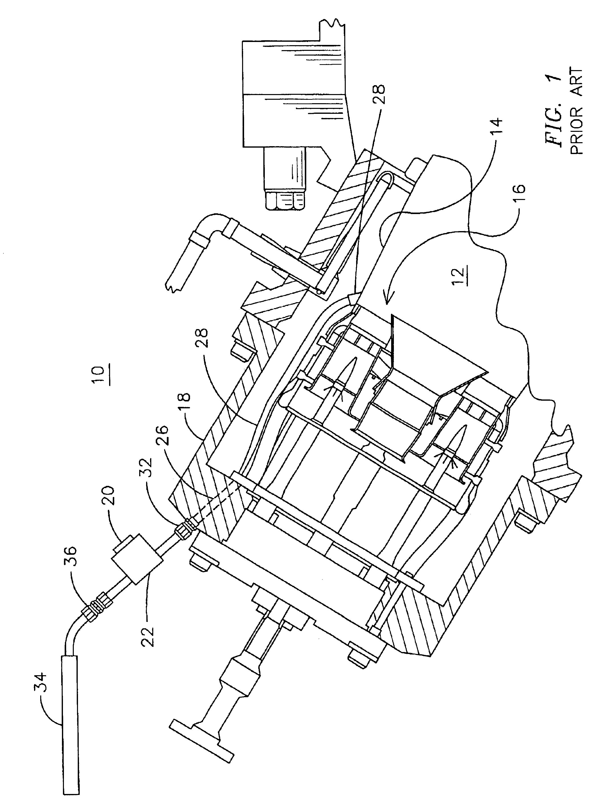
The above-cited patents depict their respective mounting arrangements in schematic fashion and do not teach or suggest the difficulties that may be encountered in securing the sensor in the correct position.
Replacement of such a pressure probe would require the disassembly of the engine case, and the wire connection may be vulnerable to mechanical damage.
If the sensor is not free to move, it may be subject to a high level of stress resulting from the differential thermal growth of the two wall members.

Method used


Image

  • Gas turbine with flexible combustion sensor connection
  • Gas turbine with flexible combustion sensor connection
  • Gas turbine with flexible combustion sensor connection

Examples


Embodiment Construction

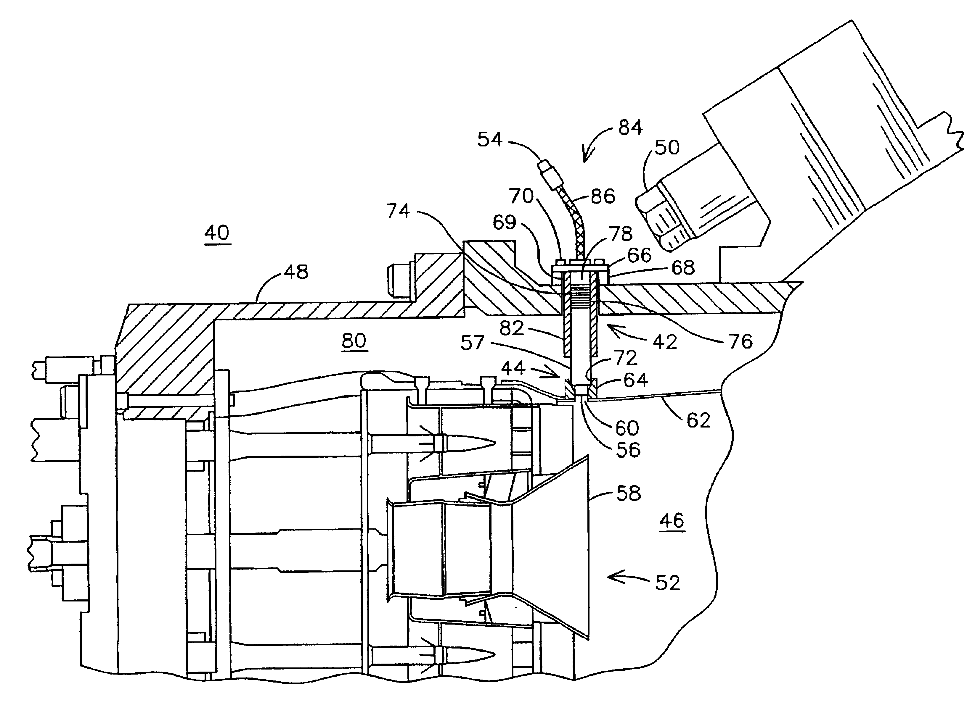
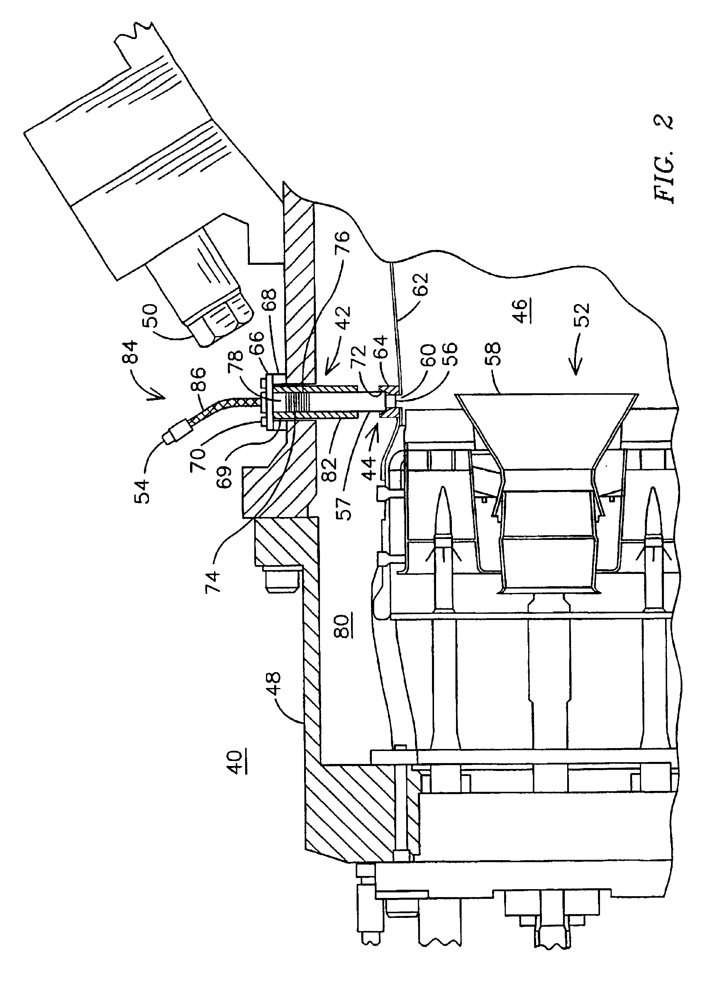
FIG. 2 is a partial cross-section view of an improved gas turbine engine 40 having a flexible mounting arrangement 42 for a sensor element 44 for detecting a parameter responsive to combustion conditions within the combustion chamber 46 of the engine 40. The sensor element 44 in the embodiment of FIG. 2 is a pressure sensor; however, one skilled in the art will recognize that other types of sensors may be used within the confines of the present invention, for example an electromagnetic radiation sensor or photo sensor, a gas sensor, a magnetic sensor, an acoustic sensor, etc.

Gas turbine engine 40 includes a casing 48 that defines a pressure boundary for the engine 40. The casing 48 is formed in sections that are joined together by a plurality of casing bolts 50. A burner assembly 52 supported within the casing 48 provides a mixture of fuel and air to the combustion chamber 46 during operation of the engine 40. Sensor element 44 forms part of an active combustion control system 54 su...


PUM


Abstract

A gas turbine engine (40) having an active combustion control system (54) including a sensor element (44) positioned proximate the combustion chamber (46) as part of a sensor assembly (84) including a spring-action bellows (74). The sensor assembly is installed through an opening (69) in the casing (48) of the engine to make contact with the combustor wall (62). The bellows is compressed from its resting position by tightening mounting bolts (70) against a mounting flange (66) of the sensor assembly. The spring action of the bellows ensures contact between the sensing assembly and the combustor wall in spite of differential thermal growth between the casing and the combustor. The sensor element may be replaced by simply removing the mounting bolts without further disassembly of the engine.

Description

FIELD OF THE INVENTIONThis application relates generally to the field of gas turbine engines and, more particularly, to a gas turbine engine having a sensor for detecting a combustion parameter.BACKGROUND OF THE INVENTIONIt is known to utilize active control of the combustion process in order to achieve stable, efficient, regulation-compliant operation of a gas turbine engine. Active control systems typically include a sensor for detecting a parameter responsive to the combustion process and a control element for controlling the combustion process in response to the measured parameter. One or more such parameters may be measured; for example, the parameter may be the pressure in the combustion chamber, a predetermined wavelength of electromagnetic energy generated by the combustion process, or the exhaust concentration of a particular combustion byproduct such as carbon monoxide.One such gas turbine with active combustion control is described in U.S. Pat. No. 5,428,951, incorporated...

Claims


Application Information

Patent Timeline
IPC IPC(8): F01D21/00F02C9/28F02C9/00
CPCF02C9/28F01D21/003
Inventor PARKER, DAVIDRYAN, WILLIAM RICHARD
Owner SIEMENS ENERGY INC
Learn More