Suspension beam and bush attachment assembly

a technology of suspension beam and bush, which is applied in the direction of resilient suspension, vehicle spring, vehicle components, etc., can solve the problems of affecting the service life of the bush, the failure of the bush to be serviced, and the failure of the entire system to be replaced prematurely, so as to reduce the distortion of the flange, the effect of easy and cost-effective service and maintenan

Inactive Publication Date: 2005-01-18
RIDEWELL
View PDF19 Cites 18 Cited by
  • Summary
  • Abstract
  • Description
  • Claims
  • Application Information

AI Technical Summary

Benefits of technology

Each control arm extends longitudinally along the vehicle and incorporates a bush end, a mid-region, and an axle mount spaced from the bush end by the mid-region therebetween. At the bush end, the bush eye clamp has a generally annular cross-section and is sized to receive a resilient bush for pivotable attachment to the vehicle chassis or a suspension hanger bracket. The bush eye clamp has a transverse slot or gap and it is preferred to be made of steel tubing or rolled sheet. The bush eye clamp is rigidly attached to the suspension beam radially on a fixed end and terminates at the transverse slot to form a free end. In this configuration, the slot is substantially adjacent to a control arm member plate. A mounting bracket is attached to the bush eye clamp proximal to the free end and the transverse slot. The mounting bracket has at least one bore that is aligned with, and opposing, corresponding bores extending through the control arm member plate. The bores of the mounting bracket and control arm are configured to receive a fastener therethrough to rigidly clamp or couple the mounting bracket, and thus the bush eye clamp free end, to the control arm. Preferably, the mounting bracket has a transversely extending flange and includes gussets to minimize flange distortion upon application of clamping forces.
As disclosed, it is desirable to service the bush in an easy and cost effective manner by means of clamping the resilient bush within the bush eye clamp with inexpensive fastening methods. Insertion of the fasteners through the control arm and adjoining mounting bracket provides a simplistic method for clamping the bush. The bush eye clamp transverse slot and corresponding gap formed between the mounting bracket and control arm prior to coupling is predetermined such that upon application of fastener clamping force, adequate compression of the bush is accomplished to prevent slippage of the bush out of the bush eye clamp during vehicle maneuvers. In the event of bush replacement, the fasteners can be easily removed and replaced.
The control arm may take on a variety of shapes, such as a closed or boxed cross-section that has upper and lower member plates and side plates to provide load carrying capability. In this configuration, an aperture is provided in the member plate opposite of the member plate having the fastener bores such that fasteners may be accessed for bush replacement. The control arm may also form a U-channel cross-section to reduce weight and manufacturing assembly time, obviating the need for the member plate aperture.
The present invention provides a control arm and bush attachment assembly that provides ease and inexpensive servicing of the bush. By simply using fasteners to clamp the bush in place, the bush may be quickly exchanged after its normal life is expended without the need of premature replacement of other suspension components. Additionally, by the use of a single mounting bracket to couple the bush eye clamp free end to the control arm and retain the bush therein, the present invention provides a lightweight design that saves material costs as compared to suspension systems employing multiple brackets for bush retention.

Problems solved by technology

The bush, often made from a hyperelastic material, is subject to periodic replacement due to wear and aging.
However, unitized systems make bush replacement difficult, and often lead to premature replacement of the entire system when only bush replacement was necessary.

Method used


Image

  • Suspension beam and bush attachment assembly
  • Suspension beam and bush attachment assembly
  • Suspension beam and bush attachment assembly

Examples


Embodiment Construction

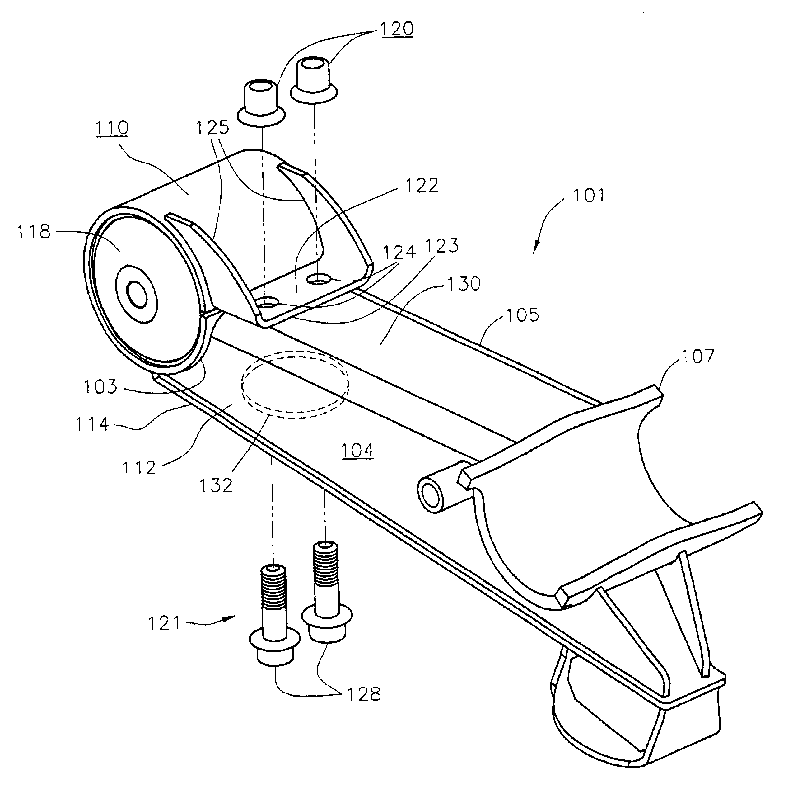
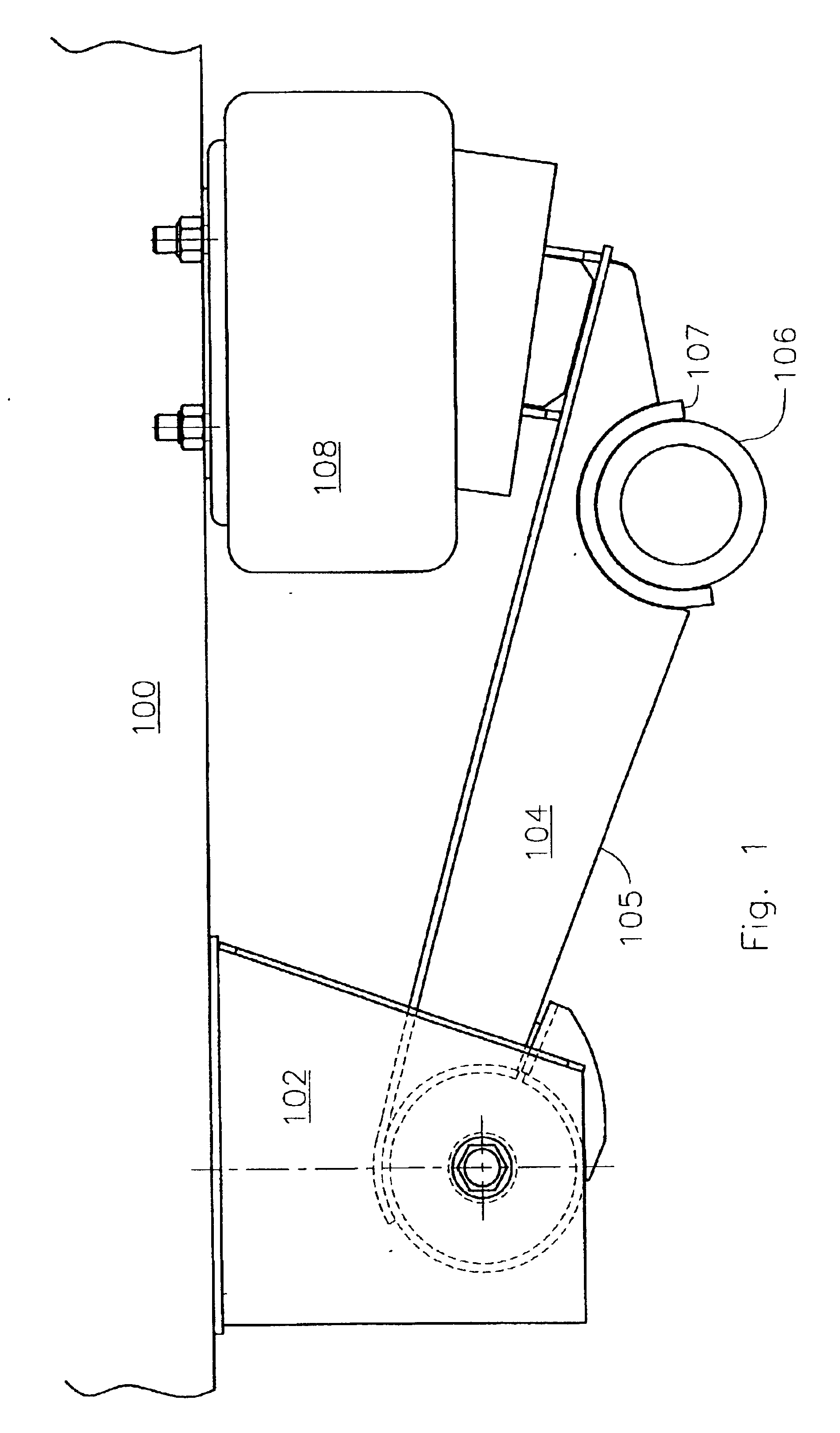
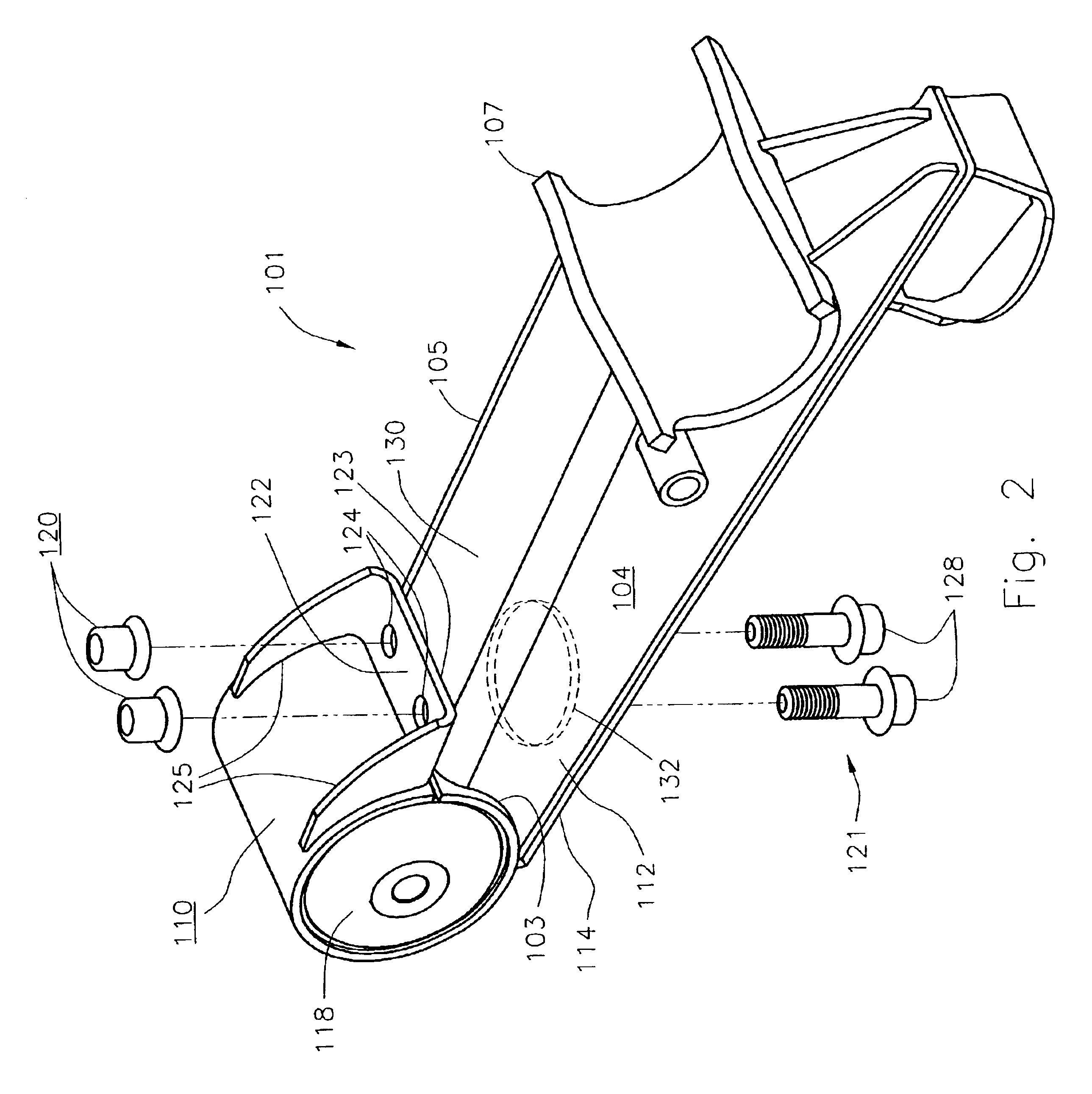
This suspension clamping system is designed for installation on a vehicle, preferably heavy trucks, trailers and commercial equipment, having a pair of substantially parallel chassis side rails. It is understood that the suspension assembly is duplicated on both sides of the chassis with the axle as well as the chassis being similarly connected to both assemblies. Since each bush clamp assembly is identical, only a single assembly will be described.

Referring now to FIG. 1, a typical hanger bracket 102 is shown attached to a vehicle chassis rails 100. A suspension beam 104, or control arm, extends longitudinally from the hanger bracket 102 along a mid-region 105 and attaches with an axle mount 107 to a spaced-apart axle 106, preferably by welding. Air spring 108, or a similar spring mechanism, mounts substantially above the suspension beam arm at its most rearward position and to the vehicle chassis rail 100. In operation, as the vehicle axle 106 and attached control arm 104 are disp...


PUM


Abstract

The present invention provides a suspension beam and bush attachment assembly. The assembly comprises a longitudinally extending control arm, a bush eye clamp, and a mounting bracket. The control arm has a bush end, a mid-region, an axle mount formed opposite of the bush end, and one or more fastener bore. The bush eye clamp is transversely mounted to the bush end of the control arm and has a center bore configured for receiving a bush therein and an axial slot biasing the bushing eye clamp open for bush insertion. To securely position the bush within the bush eye clamp, the mounting bracket is affixed to the bushing eye clamp and has one or more fastener bores substantially aligned with the one or more fastener bores of the control arm such that securing a fastener through each of the bores of the bracket and control arm couples the bracket to the control arm and biases the axial slot into a substantially closed position to contact and compress a perimeter of the bush with the bush eye clamp.

Description

FIELD OF INVENTIONThe present invention is directed vehicles suspension components, and more particularly, to a beam and bush assembly for compression fitting a bush therein.BACKGROUND OF THE INVENTIONNumerous suspension systems have been designed to attach an axle to a vehicle. Many vehicles employ suspension systems utilizing longitudinally extending trailing beams or rocker beams, also known as control arms. These beams are typically pivotally connected to the vehicle chassis or frame undercarriage at a first end, and attached to a transversely mounted axle at or near a second end. For each axle, one beam is generally located near each of the left and right sides of the vehicle. Often, a suspension member, such as an air spring, leaf spring or coil spring, is positioned between the vehicle chassis and the axle mounting end of the suspension beam. In this configuration, when the vehicle axle encounters a rough surface and is displaced by movement of the tires attached thereto, the...

Claims


Application Information

Patent Timeline
Patent Type & Authority Patents(United States)
IPC IPC(8): B60G7/02B60G9/00
CPCB60G7/02B60G9/003B60G2200/31B60G2204/44B60G2204/143B60G2204/41B60G2204/43B60G2202/152
Inventor RAIDEL, II, JOHNBARTON, BRUCEKLEIN, JASONSCAMMAHORN, EMMITT
Owner RIDEWELL
Why Eureka
Try Eureka