Constriction device including tear resistant structures

a technology of compression device and tear-resistant structure, which is applied in the field of compression device, can solve the problems of copd, no cure, and airflow obstruction in copd, and achieve the effects of preventing the propagation of tear, increasing the thickness of the sleeve, and reducing the risk of pulmonary artery diseas

Inactive Publication Date: 2005-01-18
GYRUS ACMI INC (D B A OLYMPUS SURGICAL TECH AMERICA)
View PDF11 Cites 121 Cited by
  • Summary
  • Abstract
  • Description
  • Claims
  • Application Information

AI Technical Summary

Benefits of technology

The present invention provides a constriction device that is tear resistant. The device includes an elongated sleeve having at least one opened end and being formed from elastic material to receive, when in an expanded condition, body tissue to be constricted and to constrict the body tissue when released from the expanded condition. The device further includes a tear resistance structure about the sleeve that precludes propagation of a tear in the sleeve.
The tear resistance structure may be an increased thickness of the sleeve defining a plurality of ribs in the sleeve. The plurality of ribs may include a first plurality of ribs and a second plurality of ribs which intersect each other. The intersecting ribs may define a pattern of squares, a pattern of diamonds, a pattern including waves, or a knurled pattern. Preferably the ribs are formed on an inner surface of the sleeve.
The present invention further provides a constriction device that constricts body tissue, the device including sleeve means formed of elastic material including at least one opened end for constricting body tissue received therein and tear resistance means about the sleeve for precluding propagation of a tear in the sleeve means.

Problems solved by technology

Chronic Obstructive Pulmonary Disease (COPD) has become a major cause of morbidity and mortality in the United States over the last three decades.
The airflow obstruction in COPD is due largely to structural abnormalities in the smaller airways.
COPD is a progressive disease and currently has no cure.
Unfortunately, there is no evidence that early, regular use of pharmacotherapy will alter the progression of COPD.
Unfortunately, this consideration is given for only those with advanced COPD.
Given the limited availability of donor organs, lung transplant is far from being available to all patients.
Although the surgery was deemed promising, the procedure was abandoned.
However, the procedure has fallen out of favor due to the fact that Medicare stopped remitting for LVRS.
Unfortunately, data is relatively scarce and many factors conspire to make what data exists difficult to interpret.
However, the surgery is very invasive and fraught with complications.
Among the complications is the potential for lung air leaks.
Lung tissue is very thin, and fragile hence difficult to suture together.
In about thirty percent (30%) of the cases, the difficulty with suturing lung tissue results in air leaks.
With increasing age, a patient may develop a weakened section of lung which may then rupture due to an extreme pressure differential, such as may result from simply a hard sneeze.
AIDS patients can suffer from air leaks in their lungs.
Although various methods and apparatus have been conceived for effectively deploying constriction devices on body tissue, the constriction devices, over time, may become dislodged due to the nature of the soft tissue on which they are deployed.
More specifically, soft body tissue has a tendency to expand at the proximal end of the device causing longitudinal slippage of the device on the body tissue.
This may eventually lead to the device slipping totally free from the tissue.
While suturing would appear to be an option, simply suturing the constriction device to the constricted body tissue would pose a number of problems.
Such problems would arise because the material from which the constriction device is formed is relatively thin elastic material.
The suturing of such material could easily cause tearing of the device by the suture.
Moreover, the very act of puncturing the device material with a suture needle could readily cause tearing of the device material.
While the suture hole reinforcement mentioned above represents an important advancement towards protecting the constriction device against tears during suturing, there is still the possibility that the device may be accidentally punctured or torn outside of a suture hole during deployment.

Method used


Image

  • Constriction device including tear resistant structures
  • Constriction device including tear resistant structures
  • Constriction device including tear resistant structures

Examples


Embodiment Construction

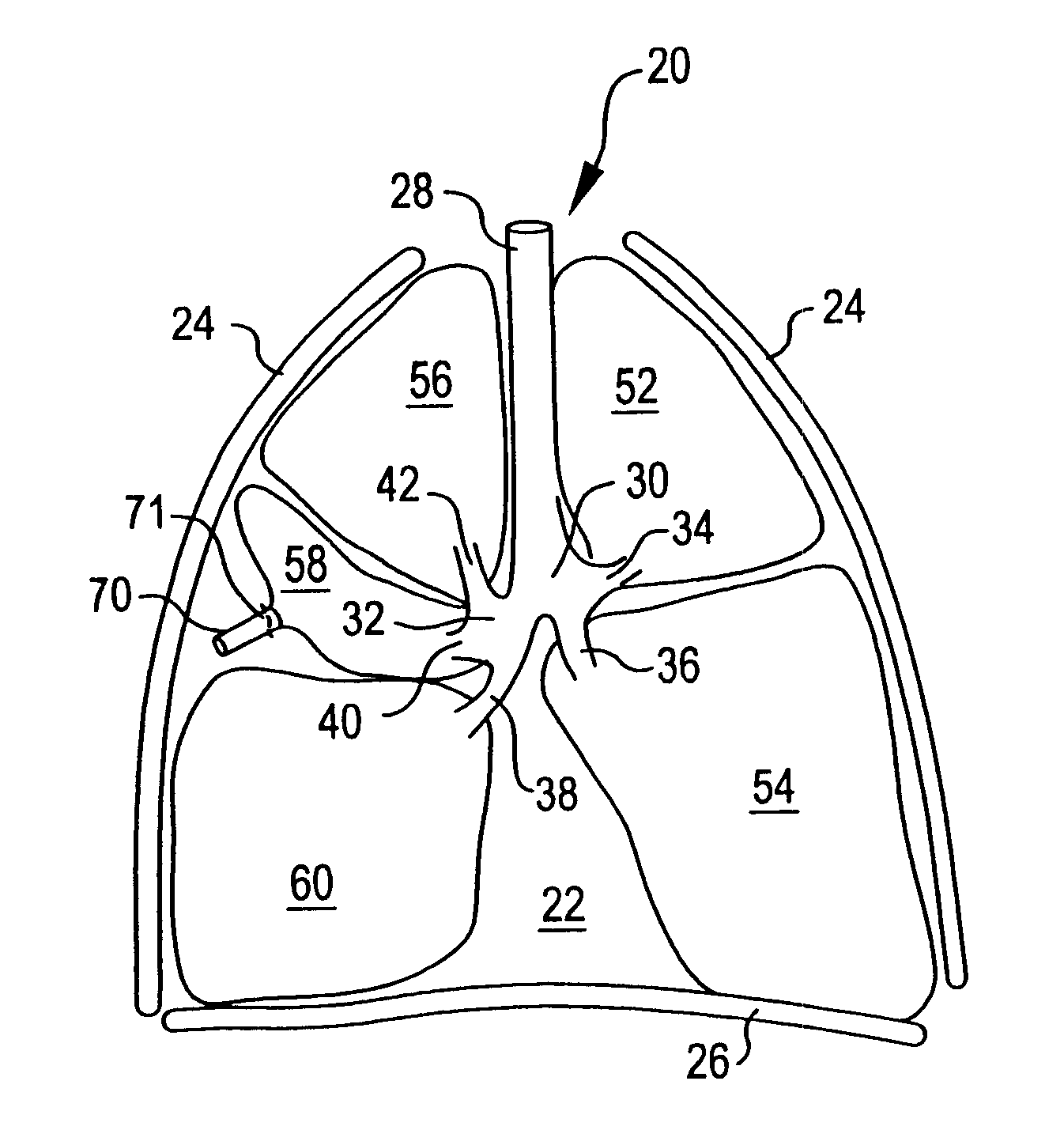
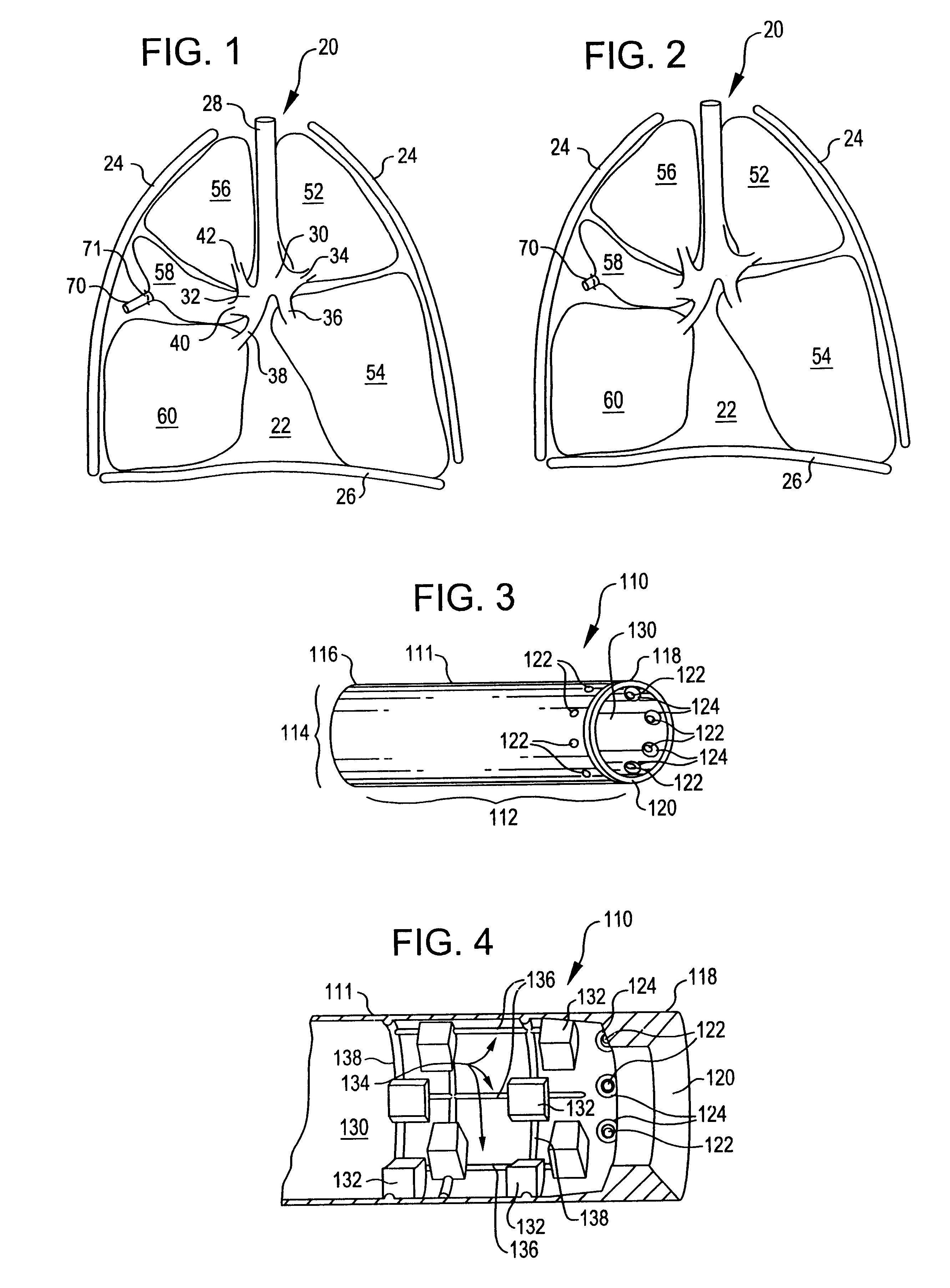
Referring now to FIG. 1, it is a sectional view of a respiratory system 20. The respiratory system 20 resides within the thorax 22 which occupies a space defined by the chest wall 24 and the diaphragm 26.

The respiratory system 20 includes the trachea 28, the left mainstem bronchus 30, the right mainstem bronchus 32, and the bronchial branches 34, 36, 38, 40, and 42. The respiratory system 20 further includes left lung lobes 52 and 54 and right lung lobes 56, 58, and 60. Each bronchial branch communicates with a respective different portion of a lung lobe, either the entire lung lobe or a portion thereof.

A healthy respiratory system has an arched or inwardly arcuate diaphragm 26. As the individual inhales, the diaphragm 26 straightens to increase the volume of the thorax 22. This causes a negative pressure within the thorax. The negative pressure within the thorax in turn causes the lung lobes to fill with air to an inflated condition. When the individual exhales, the diaphragm retur...


PUM


Abstract

A constriction device that constricts body tissue and is formed of relatively thin elastic material includes a tear resistance structure to preclude an inadvertent tear in the device from propagating through the device. The tear resistance structure includes a plurality of intersecting ribs formed in the elastic material. The ribs circumscribe the device and define rectangular, square, diamond, wavy, or knurled patterns.

Description

BACKGROUND OF THE INVENTIONThe present invention is generally directed to a constriction device that constricts body tissue. The present invention is more particularly directed to a constriction device that includes tear resistant structures to preclude propagation of a tear in the device for protecting the integrity of the constriction device.Constriction devices have been contemplated for constricting body tissue. Such devices have been considered for use, for example, in tissue resection procedures and in treating pulmonary disease.Chronic Obstructive Pulmonary Disease (COPD) has become a major cause of morbidity and mortality in the United States over the last three decades. COPD is characterized by the presence of airflow obstruction due to chronic bronchitis or emphysema. The airflow obstruction in COPD is due largely to structural abnormalities in the smaller airways. Important causes are inflammation, fibrosis, goblet cell metaplasia, and smooth muscle hypertrophy in termina...

Claims


Application Information

Patent Timeline
Patent Type & Authority Patents(United States)
IPC IPC(8): A61F13/00A61F2/00A61B19/00A61B17/00A61B17/122A61FA61F2/04
CPCA61F2/04A61B17/122A61F2002/043
Inventor CORCORAN, DEAN T.REDDY, DAVID J.
Owner GYRUS ACMI INC (D B A OLYMPUS SURGICAL TECH AMERICA)
Why Eureka
Try Eureka