Class B driver

a driver and line driver technology, applied in the field of data communication, can solve the problems of difficult to obtain stable output signals with such a circuit, inability to accurately process signals, and long rise time tsub>1/sub>,

Inactive Publication Date: 2005-01-18
MARVELL ASIA PTE LTD
View PDF29 Cites 52 Cited by
  • Summary
  • Abstract
  • Description
  • Claims
  • Application Information

AI Technical Summary

Benefits of technology

One feature of the arrangement of FIG. 21 is that the transmit signal is free of the distortion shown in FIG. 24. FIG. 25 shows a waveform produced by the circuit of FIG. 21. Because each level of the transmit signal is generated independently by similar circuits, the slew rates are the same for each signal level. Consequently, as shown in FIG. 25, the rise time t for each signal level is the same.
Another feature of the arrangement of FIG. 21 is the provision of an accurate replica of the transmit signal components produced by the VCC...

Problems solved by technology

Such interference may inhibit accurate signal processing.
The RC filter limits rise and fall times of the input signal I. However, the R and C components are typically process and/or temperature dependent.
A stable output signal is difficult to obtain with such a circuit.
This construction presents two problems.
Referring to FIG. 24 for example, the bandw...

Method used


Image

  • Class B driver
  • Class B driver
  • Class B driver

Examples


Embodiment Construction

The present invention will be described with respect to circuits and methods for shaping waveforms, and in particular, to a digital-to-analog converter (DAC) employing such a waveshaping circuit. However, as will be appreciated by those skilled in the art, the present invention is not limited to applications involving DACs, but also may be applied to other applications, such as signal processing, systems to control signal rise / fall time, signal storage, communications, etc. Moreover, while the present invention is particularly suited to applications in the read channel of a hard disk drive, many other applications will suggest themselves to persons of skill in the electrical engineering arts. Furthermore, the present invention is particularly suitable for use with the structure described in U.S. patent application Ser. No. 09 / 737,743;entitled “Active Replica Transformer Hybrid”, filed concurrently herewith, the contents of which are incorporated herein by reference.

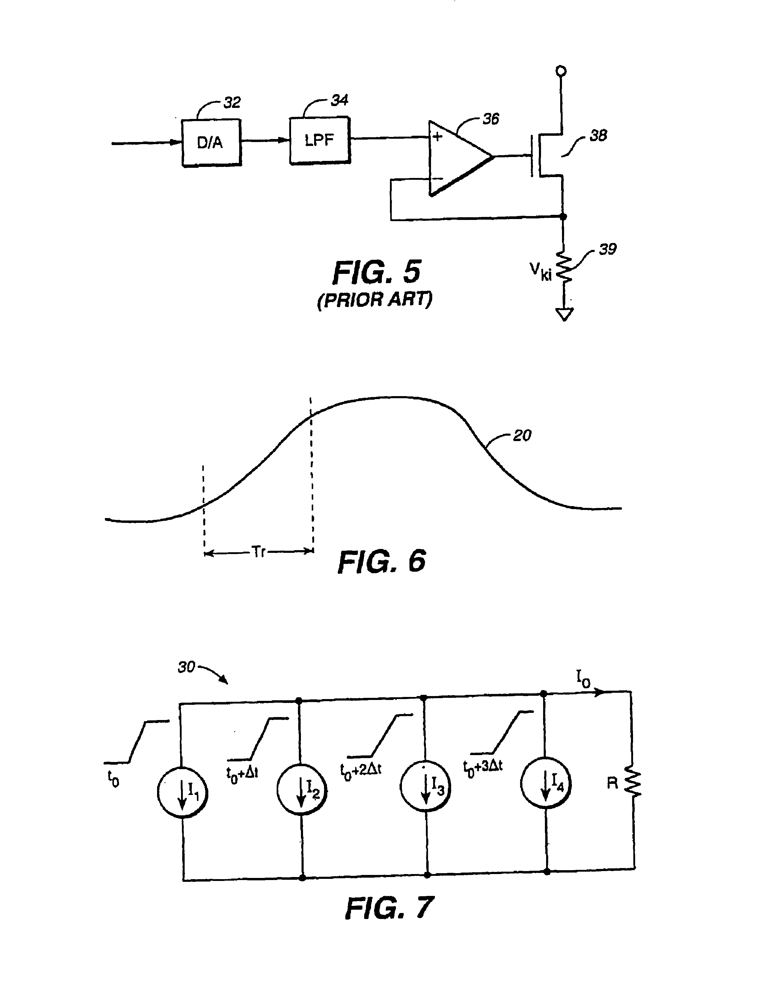
FIG. 6 illustrate...


PUM


Abstract

A communication circuit, Ethernet controller card, and method comprises K digital-to-analog converters each receiving a corresponding digital control signal and each providing a corresponding analog control signal, wherein K is at least two; K voltage-to-current converters each providing a corresponding bi-level transmit signal component in accordance with a respective one of the corresponding analog control signals; and wherein the corresponding bi-level transmit signal components of each of the K voltage-to-current converters are combined to produce a J-level transmit signal, wherein J=K+1.

Description

BACKGROUNDThe present invention relates generally to data communication. More particularly, the present invention relates to a Class B line driver for communication channels such as those present in an Ethernet network.Digital-to-analog conversion involves the process of converting digital codes into a continuous range of analog signal levels (voltage or current), for example, as discussed in Chapter 31, “D / A and A / D Converters” of The Electrical Engineering Handbook, ed. Richard C. Dorf, CRC Press 1993, the contents of which are hereby incorporated by reference. A digital-to-analog converter (hereinafter a DAC) is generally an electronic circuit that receives an n-bit codeword from an interface and generates an analog voltage or current that is proportional to the codeword.One example of a DAC is discussed in U.S. Pat. No. 5,663,728, entitled A Digital-To-Analog Converter (DAC) and Method that set Waveform Rise and Fall Times to Produce an Analog Waveform that Approximates a Piecew...

Claims


Application Information

Patent Timeline
IPC IPC(8): H03K5/01H03M1/66
CPCH03K5/01H04B1/581H03M3/504H04B3/32H04B3/23
Inventor SUTARDJA, SEHATROO, PIERTE
Owner MARVELL ASIA PTE LTD
Why Eureka
Try Eureka