Lens system installed in mobile communication terminal

a technology of mobile communication terminal and lens system, which is applied in the field of lens system installed in mobile communication terminal, can solve the problems of distortion and the length of the optical system in the lens system, the effect of high performance and compact structur

Active Publication Date: 2005-01-18
SAMSUNG ELECTRO MECHANICS CO LTD
View PDF6 Cites 54 Cited by
  • Summary
  • Abstract
  • Description
  • Claims
  • Application Information

AI Technical Summary

Benefits of technology

Therefore, the present invention has been made in view of the above problems, and it is an object of the present invention to provide a lens system with a high performance and compact structure, which comprises a small number of lenses and is installed in a mobile communication terminal.

Problems solved by technology

Accordingly, compared with a silver halide camera, the digital still camera has advantages such as immediateness and convenience, while having a disadvantage of a lower resolution of the photographed image.
The more corrected the distortion is, the greater the deterioration in the resolution becomes.
In case that the lens system is designed at an angle smaller than the desired angle, the resolution, distortion and the length of the optical system in the lens system are deteriorated, thereby causing a problem of combining the lens system with the sensor.
Further, distortion is a failure of a lens, in which a straight line of a subject is bent to form an image.
As described above, the conventional lens system employs a designated number of lenses, that is, four lenses, thereby increasing the volume of an optical system, and cost and time taken to perform a complicated assembly process.
Accordingly, using the above-described conventional lens system, it is difficult to manufacture a small-sized mobile communication terminal having a size of less than predetermined dimensions.

Method used


Image

  • Lens system installed in mobile communication terminal
  • Lens system installed in mobile communication terminal
  • Lens system installed in mobile communication terminal

Examples


Embodiment Construction

Now, preferred embodiments of the present invention will be described in detail with reference to the annexed drawings.

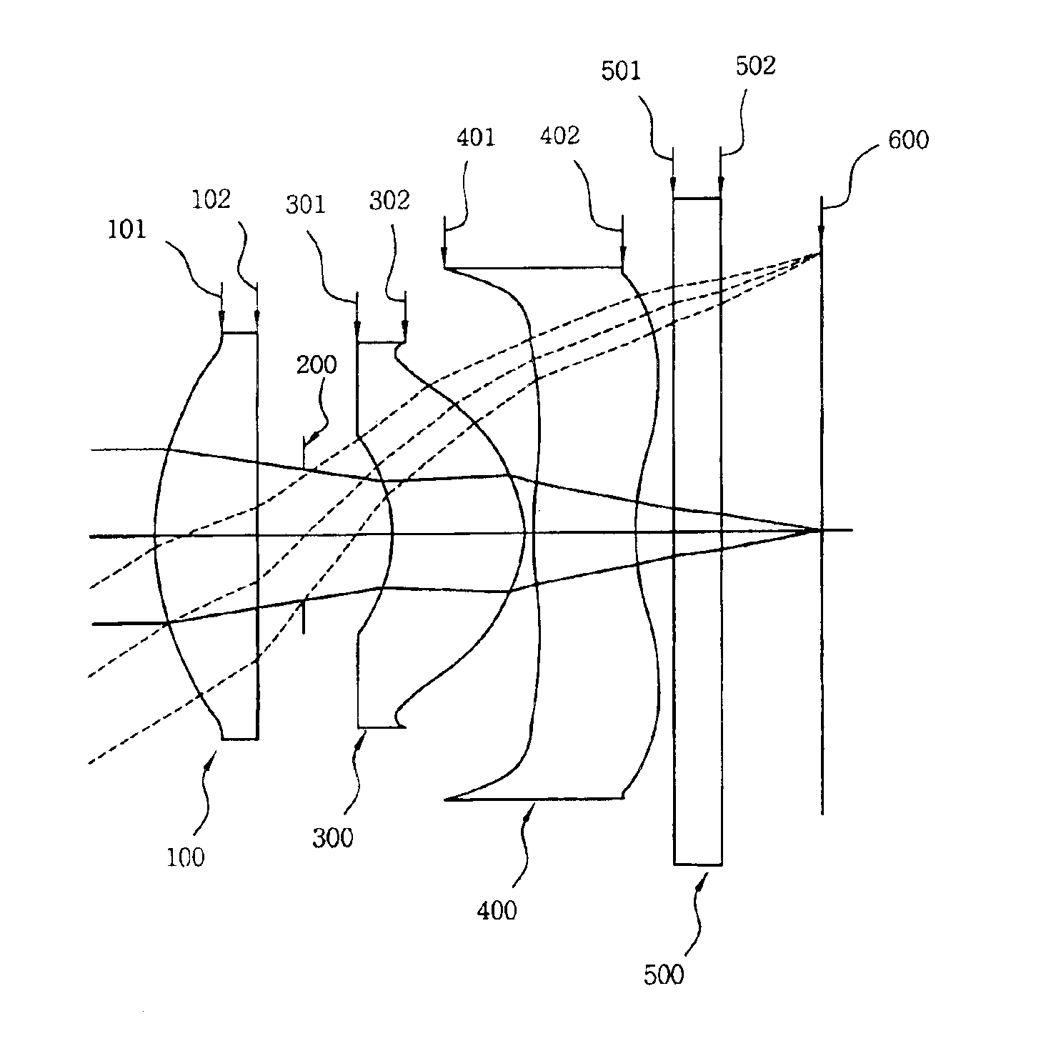
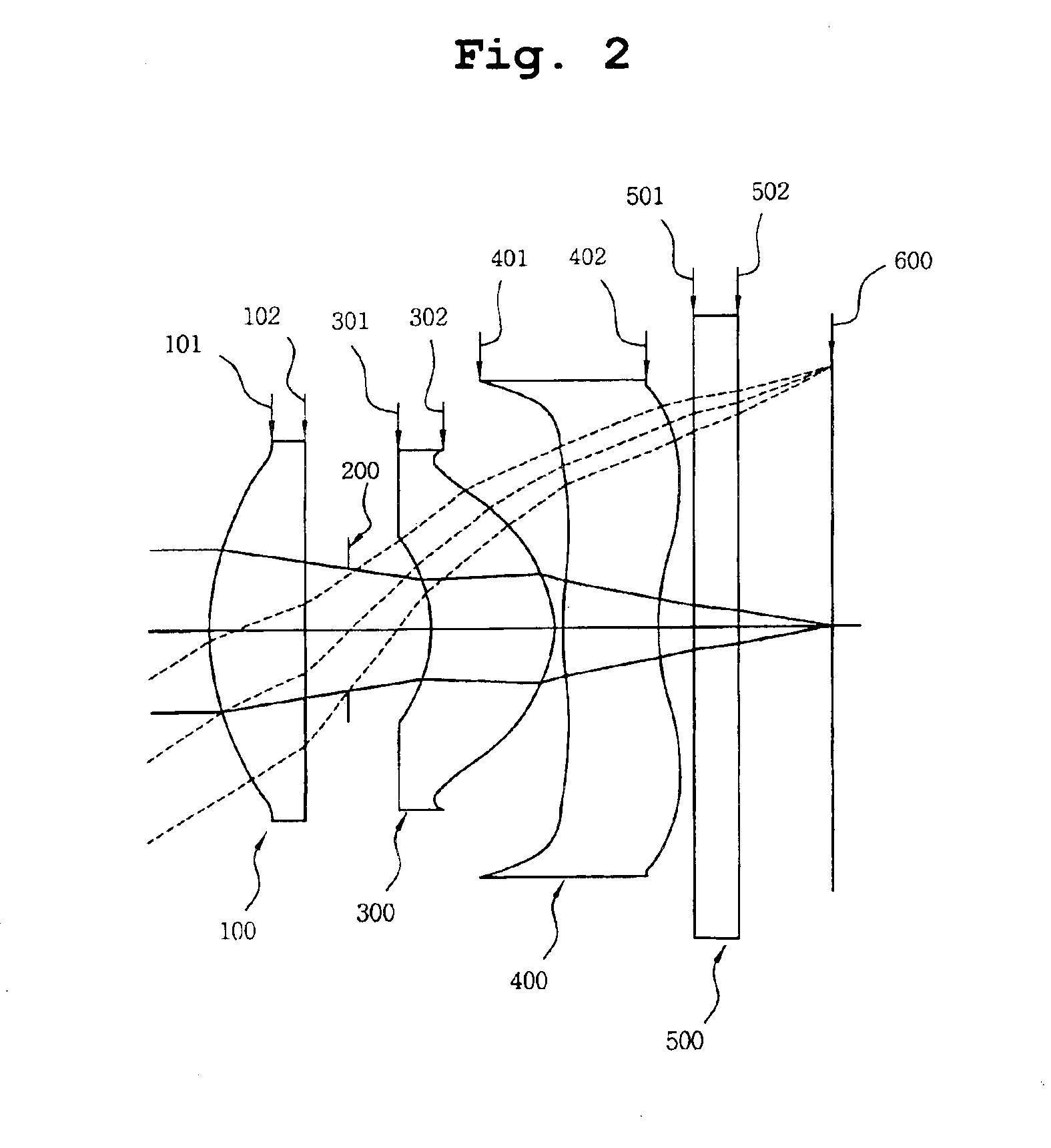
FIG. 2 is a schematic view of a lens system installed in a mobile communication terminal in accordance with the present invention. FIG. 3 is a graph illustrating spherical aberration occurring in the lens system installed in the mobile communication terminal in accordance with the present invention. FIG. 4 is a graph illustrating astigmatism occurring in the lens system installed in the mobile communication terminal in accordance with the present invention. FIG. 5 is a graph illustrating distortion occurring in the lens system installed in the mobile communication terminal in accordance with the present invention.

Hereinafter, a constitution of the lens system of the present invention will be described in detail with reference to FIG. 2.

As shown in FIG. 2, the lens system of the present invention comprises a first lens 100 having positive refractivity, a perforated i...


PUM


Abstract

Disclosed is a lens system installed in a mobile communication terminal, comprising: a first lens including at least one aspherical plane and having a positive refractivity; a perforated iris separated from the first lens by a designated distance for preventing unnecessary incident light from being incident onto an optical system; a second lens separated from the perforated iris by a designated distance, including at least one aspherical plane and having a positive refractivity; and a third lens separated from the second lens by a designated distance, including at least one aspherical plane and having a negative refractivity, wherein the first lens, the perforated iris, the second lens and the third lens are arranged sequentially from a subject, and the perforated iris is located between the first lens and the second lens.

Description

BACKGROUND OF THE INVENTION1. Field of the InventionThe present invention relates to a lens system installed in a mobile communication terminal, and more particularly to a lens system with a high performance and compact structure, which comprises a small number of lenses and is installed in a mobile communication terminal.2. Description of the Related ArtRecently, mobile communication terminal products, in which a camera is integrally installed in a mobile communication terminal, have become popular with consumers. In such a camera, a subject is photographed using a lens attached to an image pickup device such as a CCD or a CMOS, and data of the photographed subject are recorded on a recording medium.Further, a digital still camera, in which a still image formed by the lens is electrically accepted by the image pickup device including the CCD (hereinafter, referred to as “CCD”) and then recorded by an internal memory or memory card, uses a liquid crystal monitor as a finder when pho...

Claims


Application Information

Patent Timeline
Patent Type & Authority Patents(United States)
IPC IPC(8): G02B13/00H04B1/40
CPCG02B13/0035H04B1/38
Inventor JO, YONG-JOOKIM, YOUNG-JUNKIM, CHAN-SOO
Owner SAMSUNG ELECTRO MECHANICS CO LTD
Why Eureka
Try Eureka