Method for correcting the shift of output wavelength of light source

Active Publication Date: 2005-01-18
ELECTRONICS & TELECOMM RES INST
View PDF8 Cites 17 Cited by
  • Summary
  • Abstract
  • Description
  • Claims
  • Application Information

AI Technical Summary

Problems solved by technology

As described above, if the wavelength is not uniform, original data cannot be easily restored at a corresponding destination, thus hindering normal information transmission.
However, the above method of locking a wavelength continuously using the wavelength locker

Method used


Image

  • Method for correcting the shift of output wavelength of light source
  • Method for correcting the shift of output wavelength of light source
  • Method for correcting the shift of output wavelength of light source

Examples


Embodiment Construction

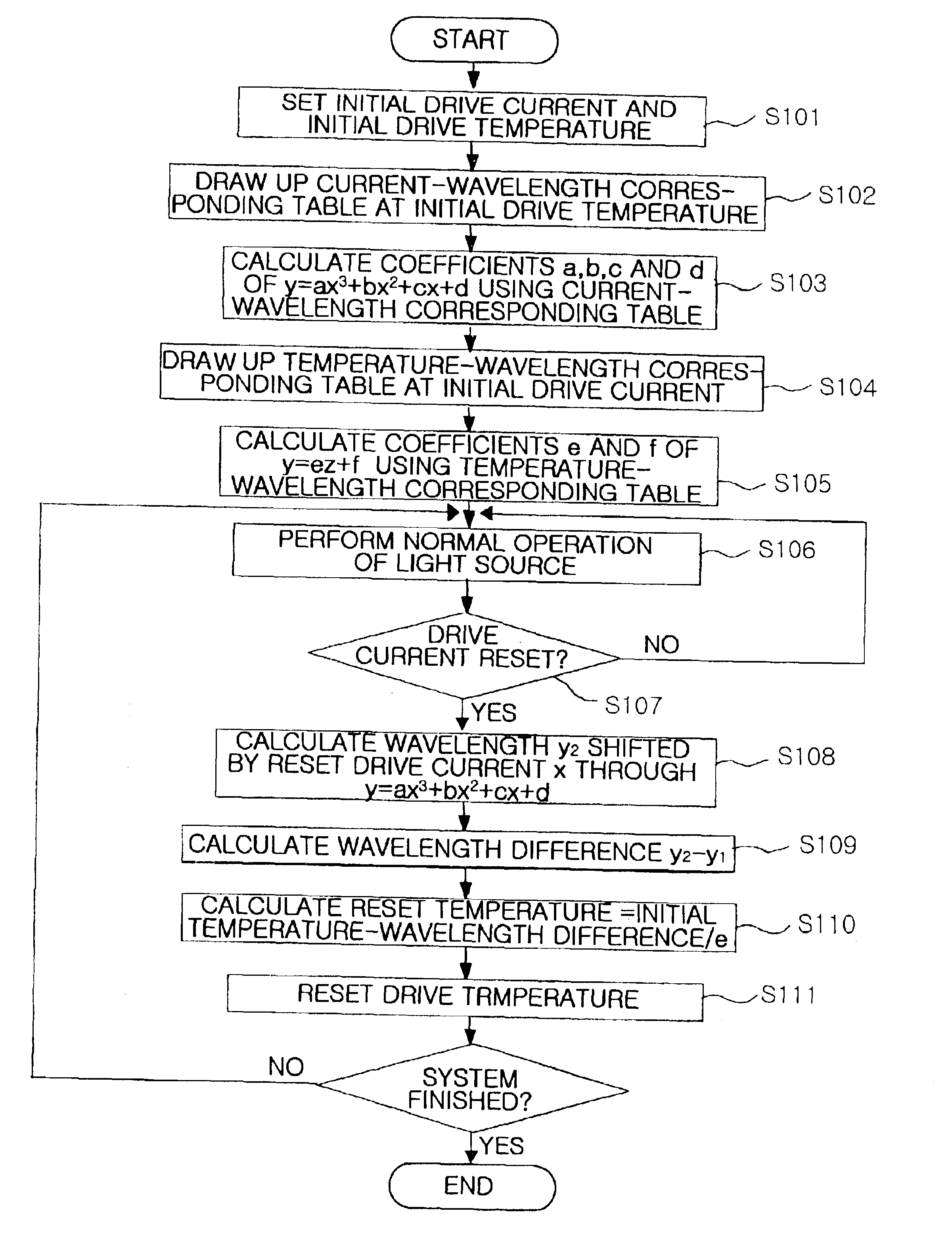
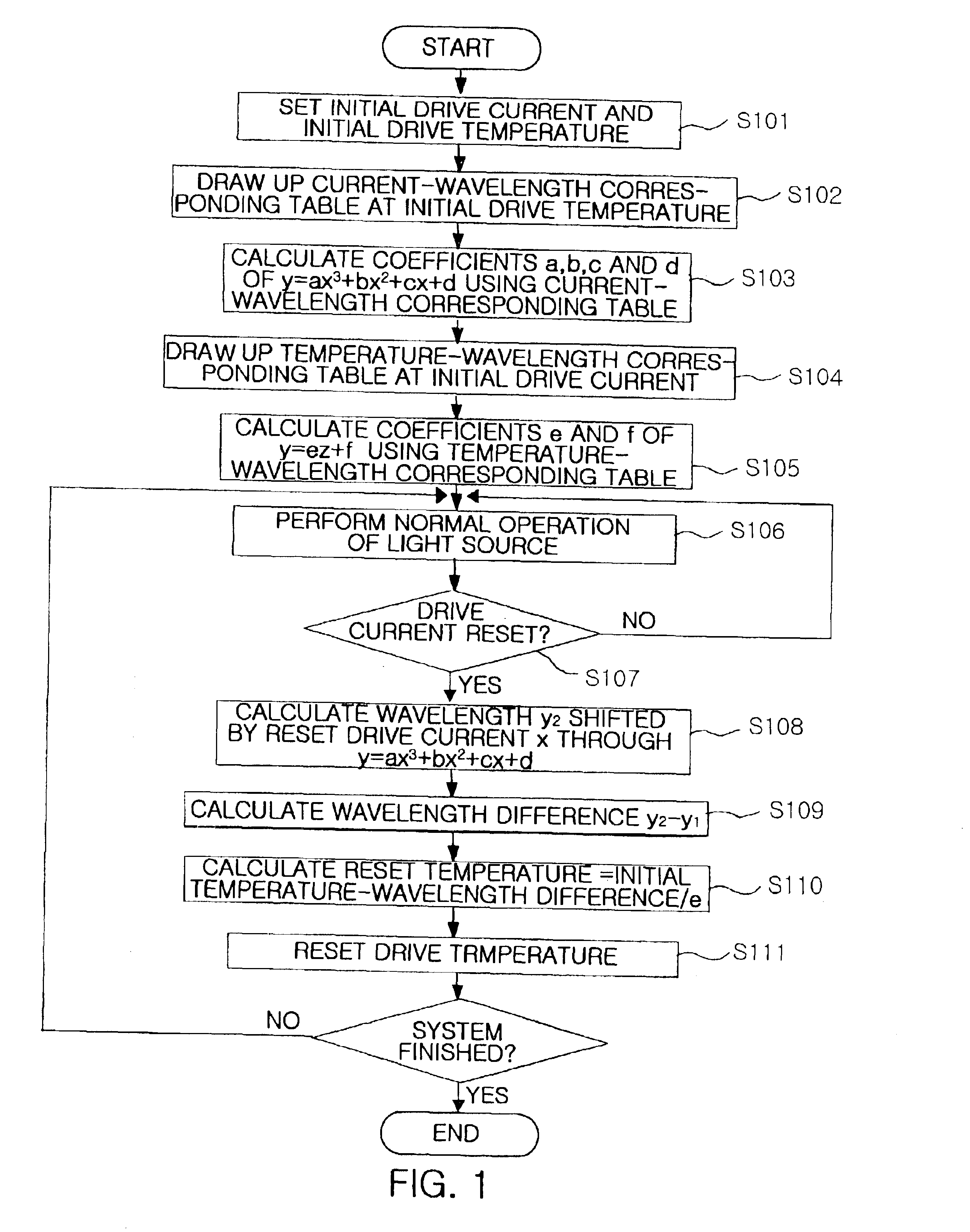
Hereinafter, embodiments of a method for correcting the shift of an output wavelength of a light source according to the present invention will be described in detail with reference to the attached drawings.

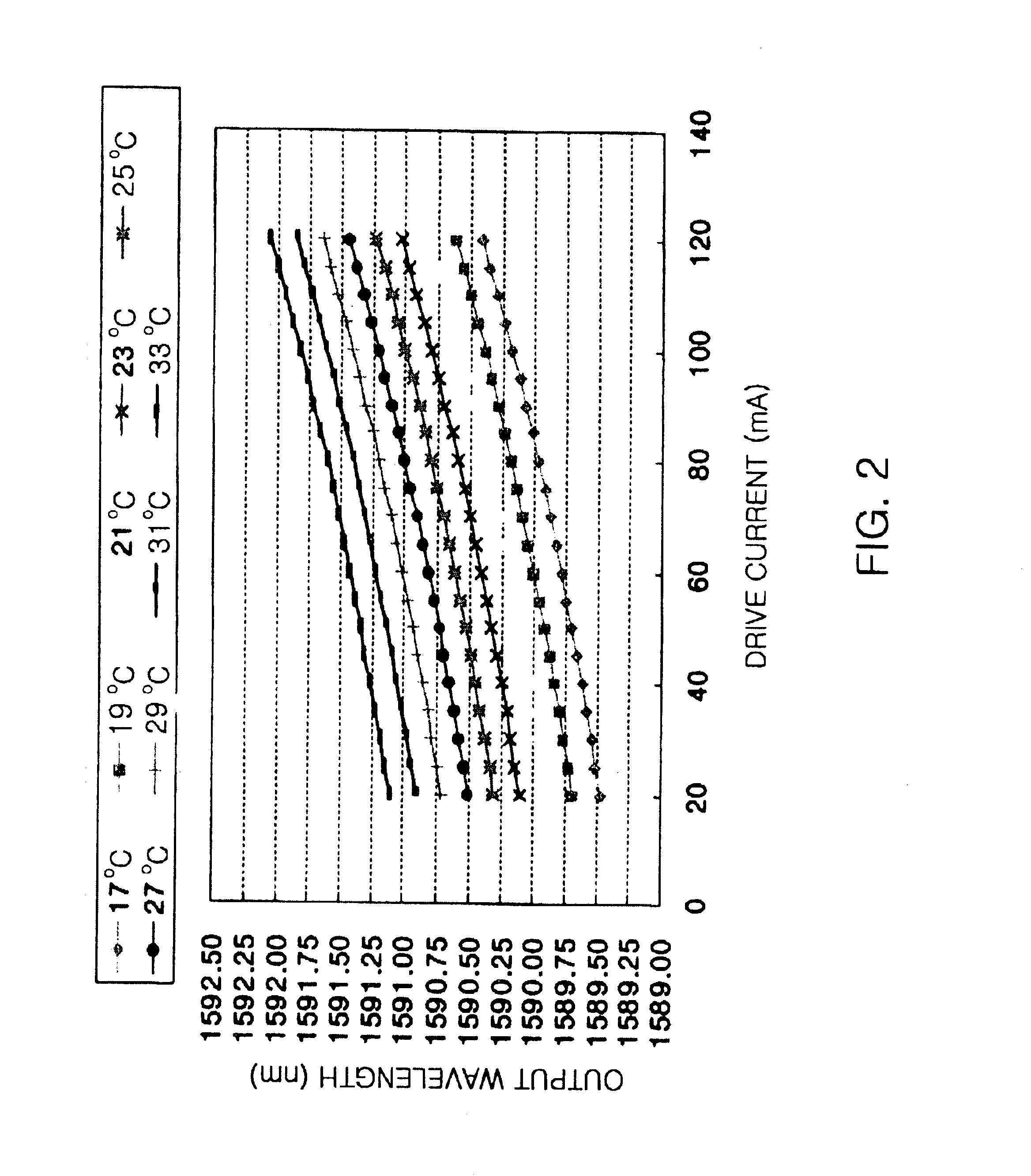
FIG. 1 is a flowchart of a method for correcting the shift of an output wavelength of a light source according to the present invention. Referring to FIG. 1, at the first step S101 of the output wavelength shift correcting method, an initial drive current and an initial drive temperature of a light source of a multi-channel light source driving apparatus used in an optical communication system are set on the basis of an output light intensity and an output wavelength which are previously set. In the optical communication system, a plurality of light sources of the multi-channel light source driving apparatus must generate and maintain different output wavelengths. For these operations, the initial drive current and the initial drive temperature suitable for the set output wavelen...


PUM


Abstract

The present invention provides a method for correcting a shift of an output wavelength of a light source. The output wavelength shift correcting method derives simple equations through experimental processes, predicts a shift degree of the output wavelength with respect to a varied input current using the equations whenever a drive current is reset later, and adjusts a drive temperature according to the predicted shift degree, thus correcting the shift of the output wavelength. The output wavelength shift correcting method is advantageous in that it provides a method of locking an output wavelength of each light source without continuously operating a wavelength locker or a wavelength measuring device, thus reducing the operating cost of the optical communication system.

Description

BACKGROUND OF THE INVENTION1. Field of the InventionThe present invention relates generally to a multi-channel optical signal transmission system for optical communication, and more particularly to a method for correcting the shift of an output wavelength generated when the intensity of output light of a light source is adjusted by a drive current of the light source in a multi-channel light source driving apparatus used in an optical communication system.2. Description of the Related ArtGenerally, optical communication technologies using optical fiber enable high speed and large capacity information transmission and do not cause signal interference or crosstalk due to electromagnetic induction, so they have been used in international communications through submarine cables. Recently, with the development of multiplexing technology and network technology, optical communication has been greatly extended in its application range to a backbone network for voice and data communications ...

Claims


Application Information

Patent Timeline
IPC IPC(8): H01S5/0687H01S5/00H01S5/06H04B10/18
CPCH01S5/0687H01S5/0612H01S5/0617H04B10/2507H04B10/572
Inventor LEE, JYUNG CHANMYONG, SEOUNG ILKO, JE SOOKANG, SEON MO
Owner ELECTRONICS & TELECOMM RES INST
Why Eureka
Try Eureka