Pre-manufactured joist and beam support for concrete walls

a technology of joists and beams, which is applied in the field of pre-manufactured joists and beam supports for concrete walls, can solve the problems of significant bending stress about the edge, unsatisfactory horizontal forces, and a large time-consuming task

Inactive Publication Date: 2005-01-25
HARBER JEROME A
View PDF9 Cites 18 Cited by
  • Summary
  • Abstract
  • Description
  • Claims
  • Application Information

AI Technical Summary

Benefits of technology

Thus the present invention is a sturdy, single part hangar that is quick and easy to install that is designed in the preferred mode to “connect” to an existing vertical rebar, if needed, or can be utilized without the rebar at the discretion of the builder, and provides for a device having a back plate member, and further is designed so as to allow a direct contact between the back plate and the concrete structure so as to disallow bending forces on the device and so as to further minimize any horizontal forces that would pull the hangar away from the wall. It is an inexpensive, easy to construct, solid single unit hangar member that can be easily intertwined with the vertical reinforcing bar members of the concrete wall if desired, and that provides for flush contact between the vertical face of the hangar and the concrete associated with the wall.
Moreover, it provides for clean connections and abutments, easily allows for beams placed at an angle such as those adjoining the wall at a 45 degree angle and allows for full concrete flow in and around the device to minimize, and essentially eliminate, air pockets of concrete that would otherwise be caused by the presence of the device.

Problems solved by technology

This method of construction presents unique problems associated with securing the next higher floor's flooring system as it connects to the top of the concrete wall.
This problem exists because most insulated concrete forms are utilized with multi-story concrete walls that comprise a continuous concrete wall from story to story.
The existing art, such as that shown in Watkins, U.S. Pat. No. 5,228,261, utilizes a multi-part device utilizing a continuous U shaped element held in place utilizing insertable / removable horizontal rebars; moreover, it requires a fairly time consuming task of cutting a specific U shaped design into the insulation material to match as closely as possible the shape of the U shaped member.
Moreover, such a hangar allows for as much as 2 to 3 inches of what is essentially open space between the concrete and the end of the joist member being supported so as to create an undesirable bending moment creating significant bending stress about the edge of the concrete wall where the device meets the concrete wall.
This bending moment has both horizontal and vertical forces, the horizontal forces of which are undesirable.
It also necessitates time and labor in tying such a device to the existing rebar structure of the concrete.
Moreover, such a device is obtrusive in terms of concrete flow inside the wall during pouring, and consequently provides an impediment in a smooth concrete flow and further provides opportunities for concrete integrity challenging air pockets to develop on the underneath sides of the channel member inside the wall.
Moreover, the ledger board is subject to shifting inasmuch as construction requires a large number of holes to match up with concrete supported bolts, a difficult to achieve task that usually results in larger than necessary holes in the ledger board creating tendencies for shifting and for weakness in the board.
Moreover, ledger boards allow for risks of rot and termite infestation and shrinkage in dry climates, all undesirable elements for key structural members.

Method used


Image

  • Pre-manufactured joist and beam support for concrete walls
  • Pre-manufactured joist and beam support for concrete walls
  • Pre-manufactured joist and beam support for concrete walls

Examples


Embodiment Construction

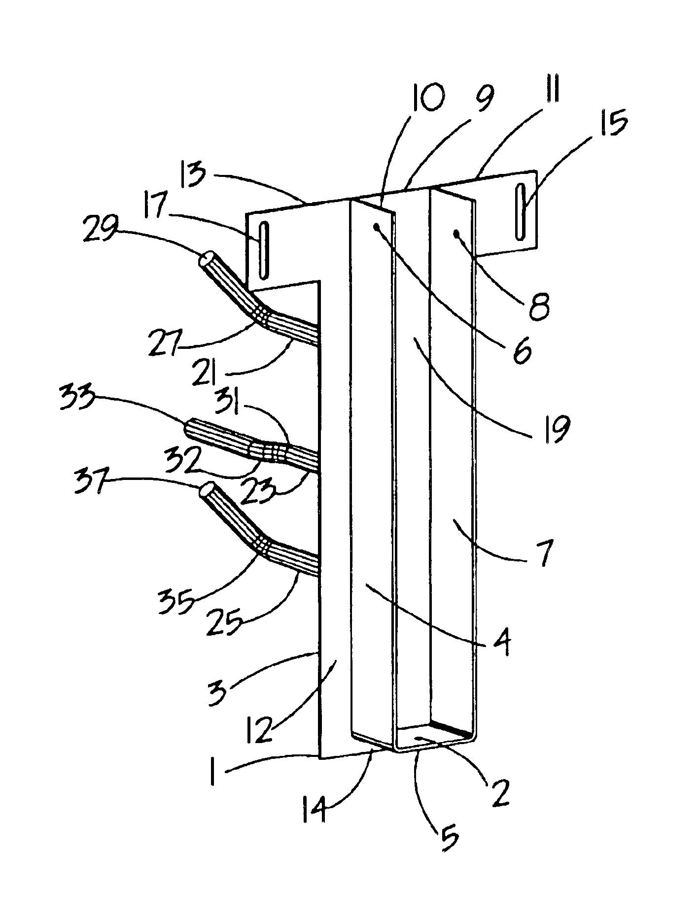
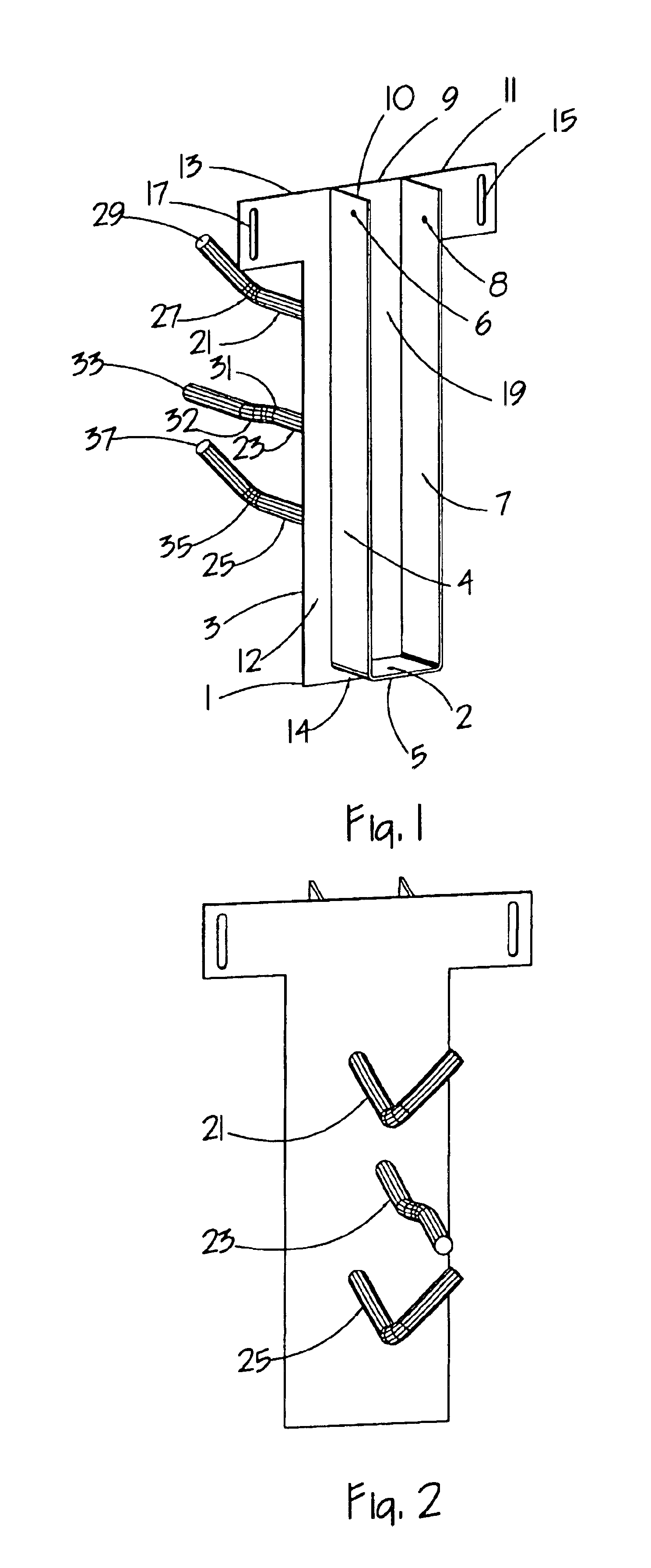
The invention is shown in the preferred mode in FIG. 1 having a U shaped channel member composed of a first elongated vertical essentially planar member 4 in essentially parallel relationship to second essentially planar member 7, having a bottom 5 there between. Back plate 9 is attached to the U shape member at its rear edges, and is essentially in its preferred mode a rigid planar T shaped member having extended wing sections 11 and 13, and further has a front face 19. This T shaped member 9 also is slightly larger than the U shaped channel member to create a side lip 12 having outer edge 3 and a corresponding opposing side lip next to the vertical wall 7 (not shown) and further creates a bottom lip 14, discussed later.

Bottom 5 has hole 2 that allows for screw, nail or other securing means to be inserted into the joist once the joist is placed in the channel member. For ease of reference throughout this specification and claims, “joist” will be used to include any floor supporting...


PUM


Abstract

A pre-manufactured joist and beam support for concrete walls to be poured, particularly those utilizing a permanent, secondary non-structural material as forms essentially adjacent to the concrete, comprised of a U shaped rigid member, rigid anchor members extending therefrom and so as to cause a sufficiently large hole to be created in the secondary material in which the support is inserted and which essentially does not interfere with the flow of concrete being poured.

Description

BACKGROUND OF INVENTIONThe present invention relates to the art of construction, in particular in connection with the integration of joist and beam supports with poured concrete walls, and more particular, those concrete walls utilizing insulated concrete forms.In the construction of buildings, residential or commercial, concrete walls are poured utilizing forms secured in place and between which the concrete is poured. Insulated concrete forms are those premanufactured forms made of sturdy spaced apart essentially planar insulating members (usually polystyrene material, commonly called styrofoam) premanufactured as a unit (in blocks, planks or panels) held together in a spaced apart fashion utilizing plastic or metal form ties. Insulated concrete forms coming in double paneled blocks, for example, are placed one on top of the other to create a double formed wall in which the concrete is poured, to create, upon curing of the concrete, not only a sturdy concrete wall, but an insulate...

Claims


Application Information

Patent Timeline
Patent Type & Authority Patents(United States)
IPC IPC(8): E04B1/26E04B1/41
CPCE04B1/41E04B1/2612
Inventor HARBER, JEROME A.
Owner HARBER JEROME A
Why Eureka
Try Eureka