Variable cycle propulsion system with gas tapping for a supersonic airplane, and a method of operation

a supersonic airplane and variable cycle technology, applied in the direction of machines/engines, marine propulsion, vessel construction, etc., can solve the problems of low specific thrust, low noise of airplane engines, and low bypass ratio of such designs, and achieve low drag and high bypass ratio

Inactive Publication Date: 2005-01-25
SN DETUDE & DE CONSTR DE MOTEURS DAVIATION S N E C M A
View PDF12 Cites 50 Cited by
  • Summary
  • Abstract
  • Description
  • Claims
  • Application Information

AI Technical Summary

Benefits of technology

Thus, the propulsion assembly dedicated to takeoff, landing, and subsonic cruising flight uses resources (gas generator) of the engines that are dedicated to supersonic cruising flight. Said propulsion assembly comprises one or more fans driven by gas tapped from the engine(s). The fans can be housed within the airplane fuselage or they can be retractable, thus enabling them to be of dimensions sufficient for producing the necessary thrust with a high bypass ratio, while nevertheless retaining low drag in supersonic flight.

Problems solved by technology

When designing a supersonic commercial airplane, there arises the particular problem of keeping airplane engine noise low during takeoff, climbing, and landing.
Such an exhaust speed thus implies an engine having low specific thrust, which corresponds to a large bypass ratio, i.e. a high level of drag when cruising at supersonic speed.
Various variable cycle engine designs are known, however varying the bypass ratio of such designs does not enable good optimization both in the subsonic configuration and in the supersonic configuration.
The propulsion assembly is constituted by retractable high-bypass ratio booster turbojets, which presents numerous drawbacks, in particular concerning bulk and weight for the airplane.

Method used


Image

  • Variable cycle propulsion system with gas tapping for a supersonic airplane, and a method of operation
  • Variable cycle propulsion system with gas tapping for a supersonic airplane, and a method of operation
  • Variable cycle propulsion system with gas tapping for a supersonic airplane, and a method of operation

Examples


first embodiment

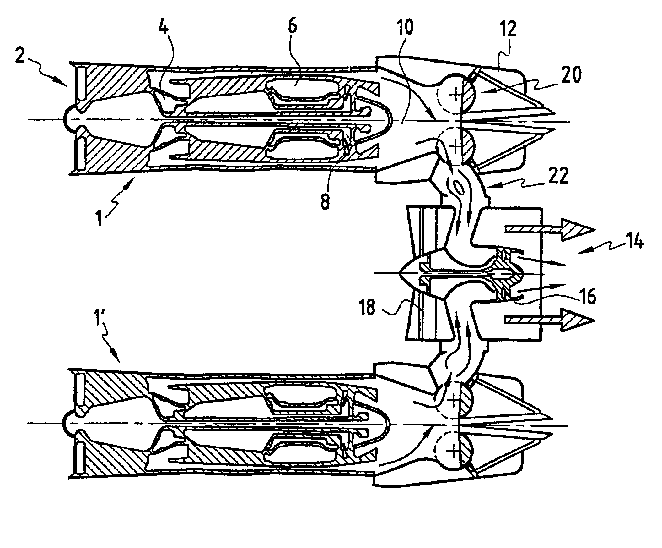
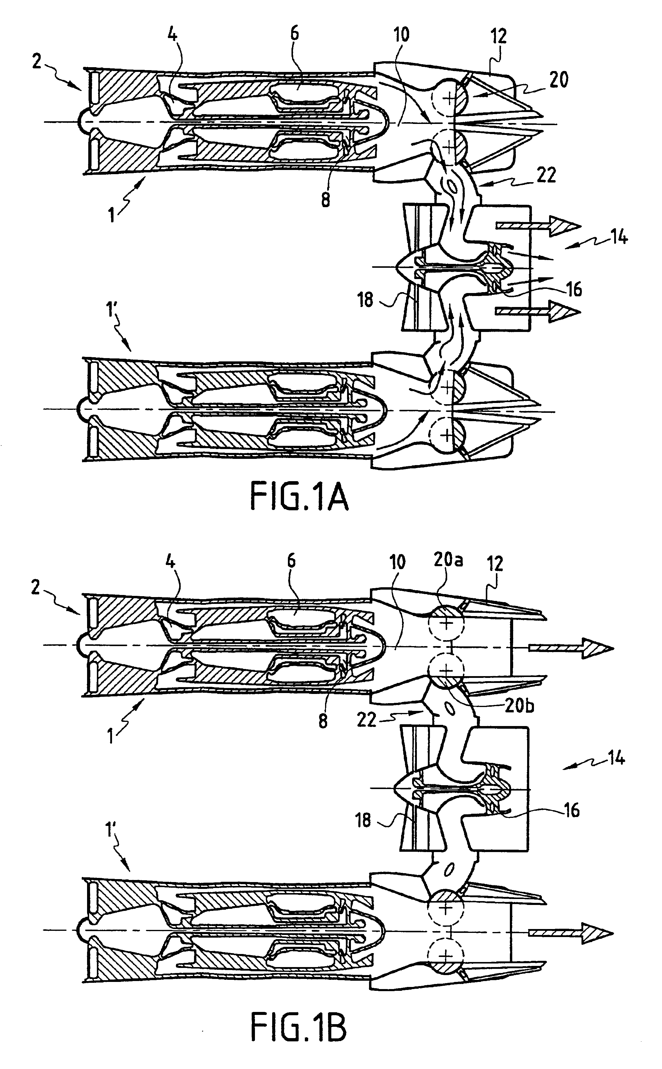
With reference to FIGS. 1A and 1B, which are diagrammatic longitudinal section views through a system constituting the invention, it can be seen that the system is constituted in particular by two engines 1 and 1′. These engines are conventionally disposed in low-drag pads (not shown) which are generally connected to the bottom faces of the wings of an airplane, but which could equally well be installed on the top faces of the wings.

In conventional manner, the engines can be of the single-flow type, having one, two or three shafts, or of the double-flow type, having one, two or three shafts. In this embodiment, each engine comprises an air intake 2, a compressor section 4, a combustion chamber 6, a turbine section 8, and a combustion gas exhaust section 10. The engines are also dimensioned optimally for supersonic cruising flight (the period involving the longest flying time).

The combustion gas exhaust section 10 is terminated with a variable geometry nozzle 12 that is axially symme...

second embodiment

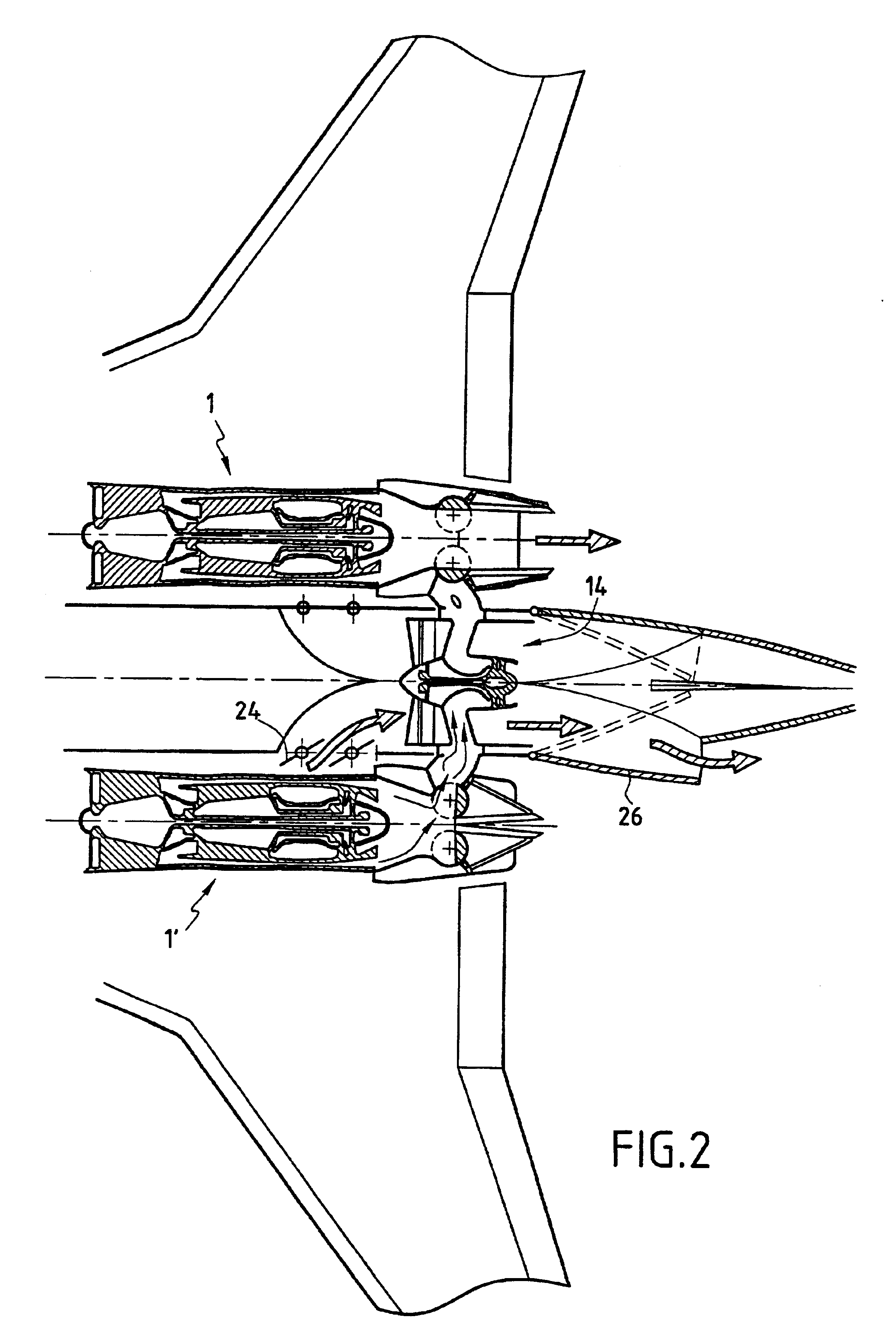
In the invention, shown in FIG. 3, the propulsion system comprises three engines 1, 1′, and 1″) feeding a single propulsion assembly 14 that is separate and dissociated from all three engines. As in the embodiment shown in FIG. 2, the propulsion assembly in this embodiment is directly integrated in the rear portion of the airplane, and a deployable exhaust nozzle 26′ is provided for exhausting the gases and producing the thrust needed for takeoff, landing, and subsonic cruising flight. In this example, it can be seen that two of the engines (1′ and 1″) are located beneath the wings of the airplane, while the third engine (1) is mounted at the root of the tailplane 28.

The tubes connecting the exhaust sections of the engines to the turbines of the propulsion assembly 14 open out into said assembly via sectors that are advantageously isolated from one another. Thus, in the event of one of the engines failing, there is no risk of the gas produced by the other two engines penetrating int...


PUM


Abstract

A variable cycle propulsion system for a supersonic airplane, the system comprising at least one engine having means for producing exhaust gas and a gas exhaust nozzle for generating thrust for supersonic flight speeds, and at least one separate auxiliary propulsion assembly dissociated from said engine, having no gas generator, and capable of generating thrust for takeoff, landing, and subsonic flight speeds. The system further comprises gas flow tapping means movable between a position in which they tap off at least a fraction of the exhaust gas produced by said engine and feed it to said propulsion assembly to enable it to generate thrust for takeoff, landing, and subsonic cruising flight, and a position in which the gas produced by the engine is directed solely to the engine nozzle for supersonic cruising flight.

Description

BACKGROUND OF THE INVENTIONThe present invention relates to a variable cycle propulsion system for a supersonic airplane making it possible both to obtain high thrust and a large bypass ratio for takeoff, landing, and subsonic cruising flight so as to greatly reduce and improve specific consumption during these stages of flight, and also to obtain a high exhaust speed adapted to supersonic cruising flight.More particularly, the invention relates to a propulsion system having auxiliary fans separate from the engines and adapted to subsonic flight (in terms both of noise and fuel consumption).In another aspect of the invention, it also relates to a method of operating said variable cycle propulsion system.When designing a supersonic commercial airplane, there arises the particular problem of keeping airplane engine noise low during takeoff, climbing, and landing. In order to be certified, all airplanes must nowadays comply with low-noise regulations for takeoff and landing.Furthermore...

Claims


Application Information

Patent Timeline
Patent Type & Authority Patents(United States)
IPC IPC(8): F02K3/075F02K3/12F02K3/00F02K3/02B64C30/00F02C3/10F02C7/36F02K1/12
CPCF02K3/025F02K3/12F02K3/075Y02T50/60
Inventor FRANCHET, MICHELLAUGIER, YANNLOISY, JEAN
Owner SN DETUDE & DE CONSTR DE MOTEURS DAVIATION S N E C M A
Why Eureka
Try Eureka