Electric power and cooling system for an aircraft

Inactive Publication Date: 2005-01-25
HAMILTON SUNDSTRAND CORP
View PDF13 Cites 48 Cited by
  • Summary
  • Abstract
  • Description
  • Claims
  • Application Information

AI Technical Summary

Benefits of technology

It is an object of the present invention to provide an electric power and cooling system for an aircraft which provides condition

Problems solved by technology

However, under normal in flight operating conditions, the burden of providing electricity and pressurized air stall falls on the main engines.
Although these systems eliminate the parasitic loss due to the

Method used


Image

  • Electric power and cooling system for an aircraft
  • Electric power and cooling system for an aircraft
  • Electric power and cooling system for an aircraft

Examples


Embodiment Construction

)

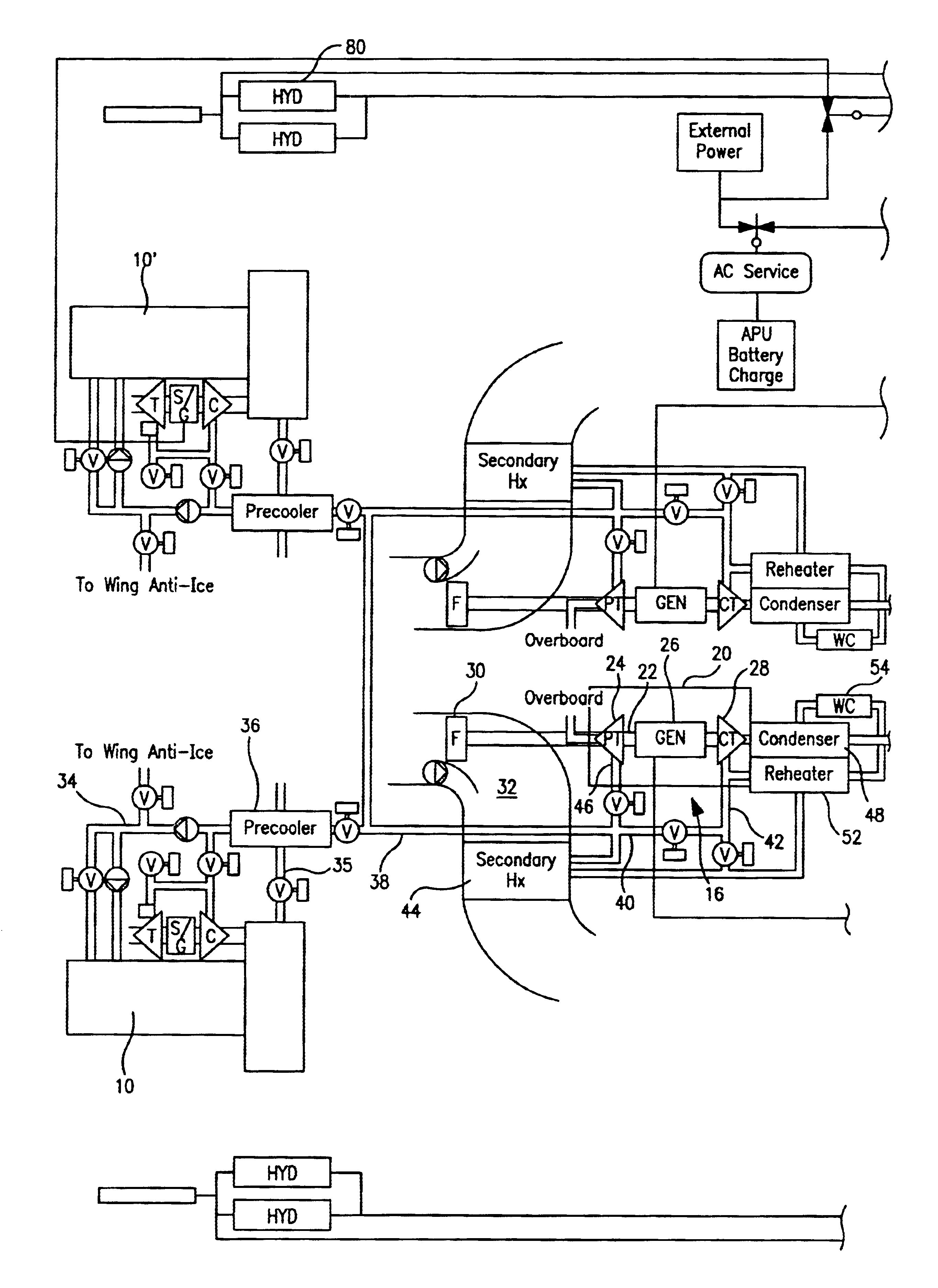
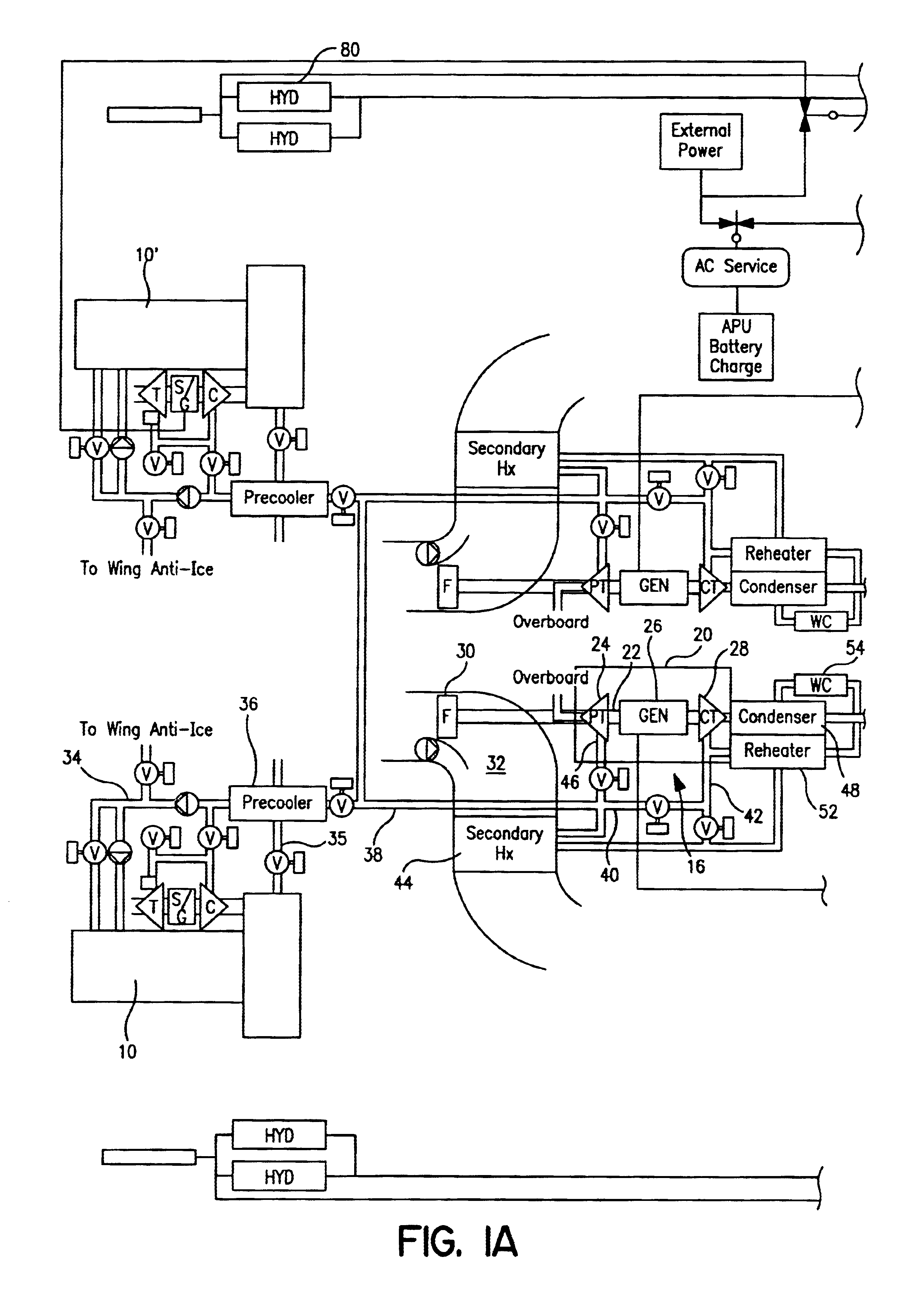
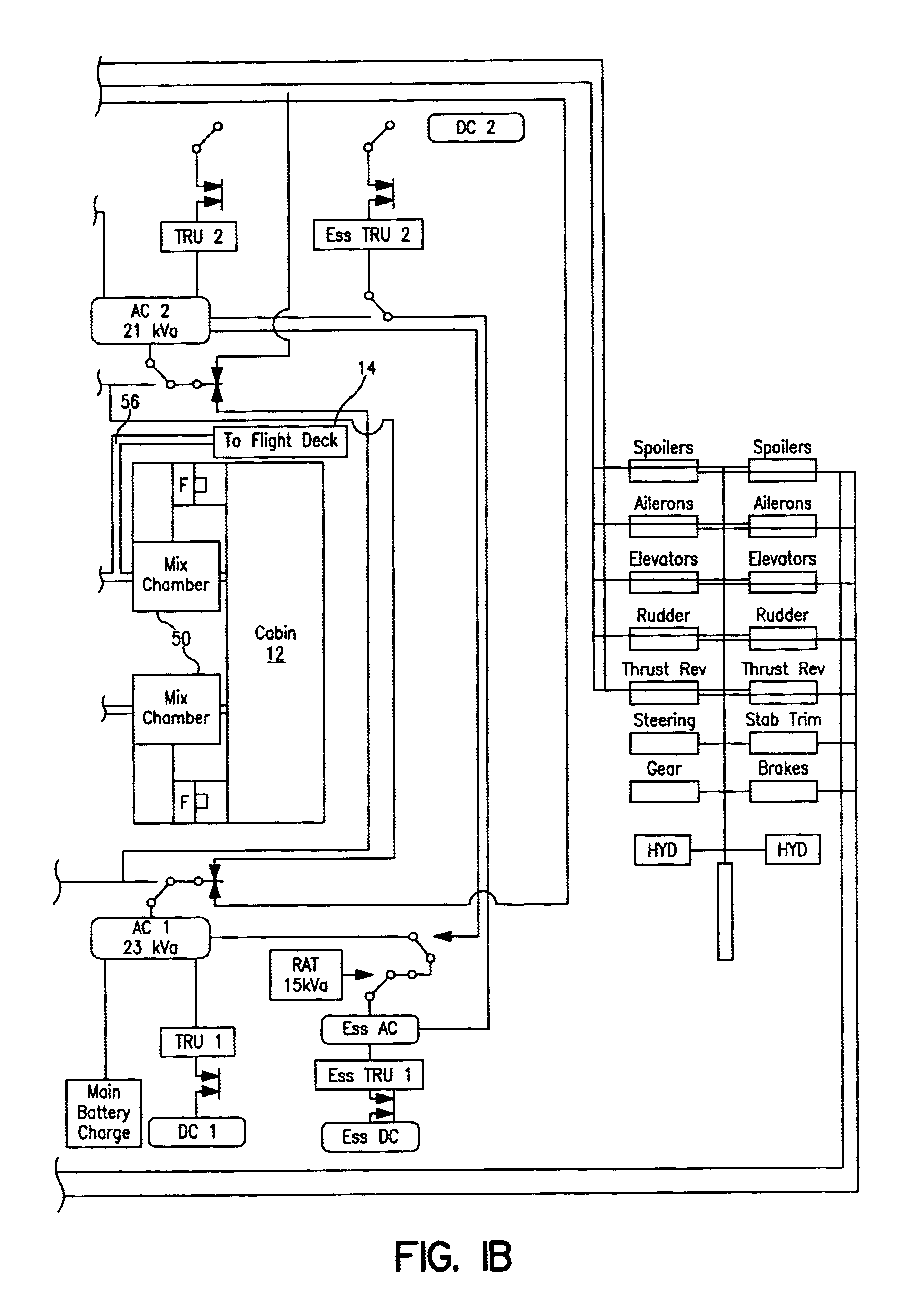
Referring now to FIGS. 1A and 1B, in this embodiment, the aircraft has at least two engines 10 and 10′. The engines 10 and 10′ may comprise any suitable jet engine known in the art. The aircraft also has a main cabin 12 and a flight deck 14 which need to be provided with conditioned air. Still further, the aircraft has a number of electrical systems which need to be supplied with electrical power. The electric power and cooling system 16 of the present invention provides conditioned air to the cabin 12 and the flight deck 14 and provides electric power to the aircraft's electrical systems.

The electric power and cooling system 16 includes an electrical power and cooling unit 20. The unit 20 has a single rotating shaft 22 which may be journaled on non-oil lubricated bearings, such as air bearings, or magnetic bearings, or any other suitable bearings known in the art. The unit includes a power turbine 24 mounted to the shaft 22, an electric generator 26 mounted to the shaft 22, and a ...


PUM


Abstract

The present invention relates to an electrical power and cooling system for use in an aircraft having at least one engine. The electrical power and cooling system comprises a single shaft, a power turbine mounted on the shaft for receiving fresh pressurized air from the at least one engine, a cooling turbine mounted on the shaft and receiving the fresh pressurized air from the at least one engine, a generator mounted on the shaft, and a fan mounted on the shaft for creating a flow of cooling air. The system further has a condenser for removing moisture from the air exiting the cooling turbine and a mixing chamber for mixing the cooled dry air with recirculated cabin air. The electrical power and cooling system delivers conditioned air to a cabin and/or a flight deck onboard the aircraft and electrical power to the aircraft's electrical systems.

Description

BACKGROUND OF THE INVENTIONThe present invention relates to an electric power and cooling system for use on an aircraft.In addition to propulsion, an aircraft's main engines provide shaft power to drive accessories such as electric generators and pumps, and fresh, pressurized air for the aircraft's environmental control system. This air is used to cool or heat, ventilate, and pressurize the aircraft cabin. The extraction of pressurized air and shaft power from the main engine is referred to as parasitic loss, and must be compensated for by increasing fuel consumption. Not surprisingly, aircraft and engine designers are continuously working on reducing these parasitic losses, and hence reducing the fuel consumption of the main engines.When the aircraft is on the ground and the main engines are shut down, many aircraft employ an auxiliary power unit. An auxiliary power unit is a small gas turbine engine comprising one or more compressors and a turbine mounted on a shaft. A combustor i...

Claims


Application Information

Patent Timeline
IPC IPC(8): B64D13/06B64D13/00
CPCB64D13/06Y02T50/56B64D2013/0644B64D2013/064Y02T50/50
Inventor BRUNO, LOUIS J.LENTS, CHARLES E.SAHM, MICHAEL K.THRESHER, WAYNE A.
Owner HAMILTON SUNDSTRAND CORP
Why Eureka
Try Eureka