
Method of utilizing multiple fuel injections to reduce engine emissions at idle

a technology of multiple fuel injection and engine, applied in the direction of machines/engines, mechanical equipment, electric control, etc., can solve the problems of increasing hydrocarbon and particulate emissions, and vice versa, and engineers have difficulty in adjusting timing and quantity, etc., to and reduce nox and smoke emissions

Inactive Publication Date: 2005-01-25
CATERPILLAR INC
View PDF8 Cites 14 Cited by
  • Summary
  • Abstract
  • Description
  • Claims
  • Application Information

AI Technical Summary

Benefits of technology

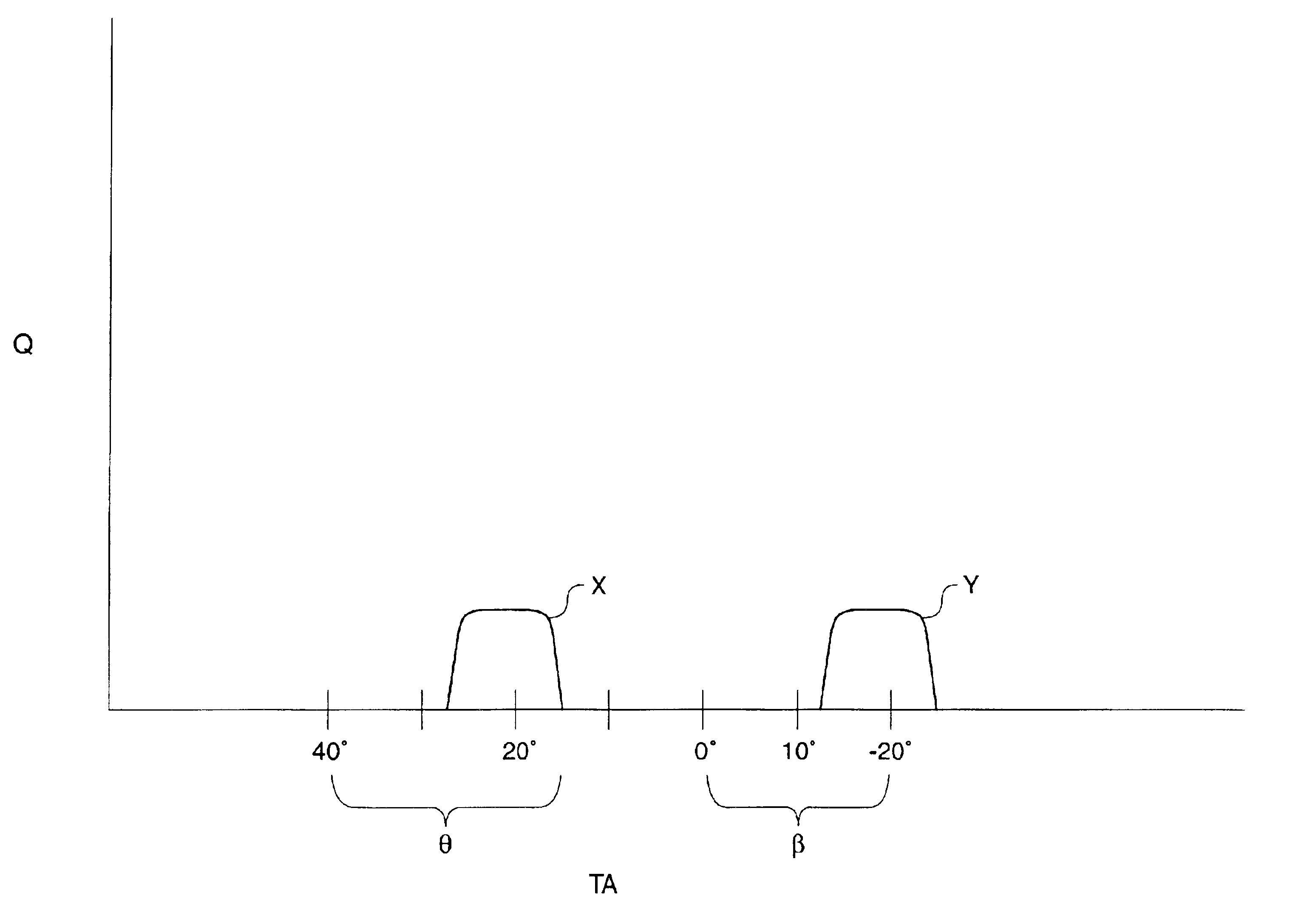
In another aspect of the present invention, there is a method of reducing NOx and smoke emissions from an engine at idle. First, the NOx emissions are reduced, at least in part, by injecting a first quantity of fuel during a compression stroke. After the first quantity of fuel has been burned, smoke emissions are reduced, at least in part, by injecting a second quantity of fuel.

Problems solved by technology

However, engineers have often found that adjustments in the fuel injection system that result in a reduction of NOx emissions may result in an increase of hydrocarbon and particulate emissions, and vice versa.
Thus, the pressure acting on the opening hydraulic surface of the needle valve member is insufficient to hold open the nozzle outlets and continue with the injection event.
Moreover, because the two shots of fuel are determined by component geometry rather than electronic control, engineers have difficulty in adjusting the timing and the quantity of each shot to further reduce NOx, hydrocarbon and smoke emissions.
Because it is difficult to control the quantity of fuel spilled through the spill port between shots, the quantity of fuel being injected into each engine cylinder varies between fuel injectors and injection events, causing the engine to exhibit unsteady behavior when operating at idle that can be irritating to an operator.

Method used


Image

  • Method of utilizing multiple fuel injections to reduce engine emissions at idle
  • Method of utilizing multiple fuel injections to reduce engine emissions at idle
  • Method of utilizing multiple fuel injections to reduce engine emissions at idle

Examples


Embodiment Construction

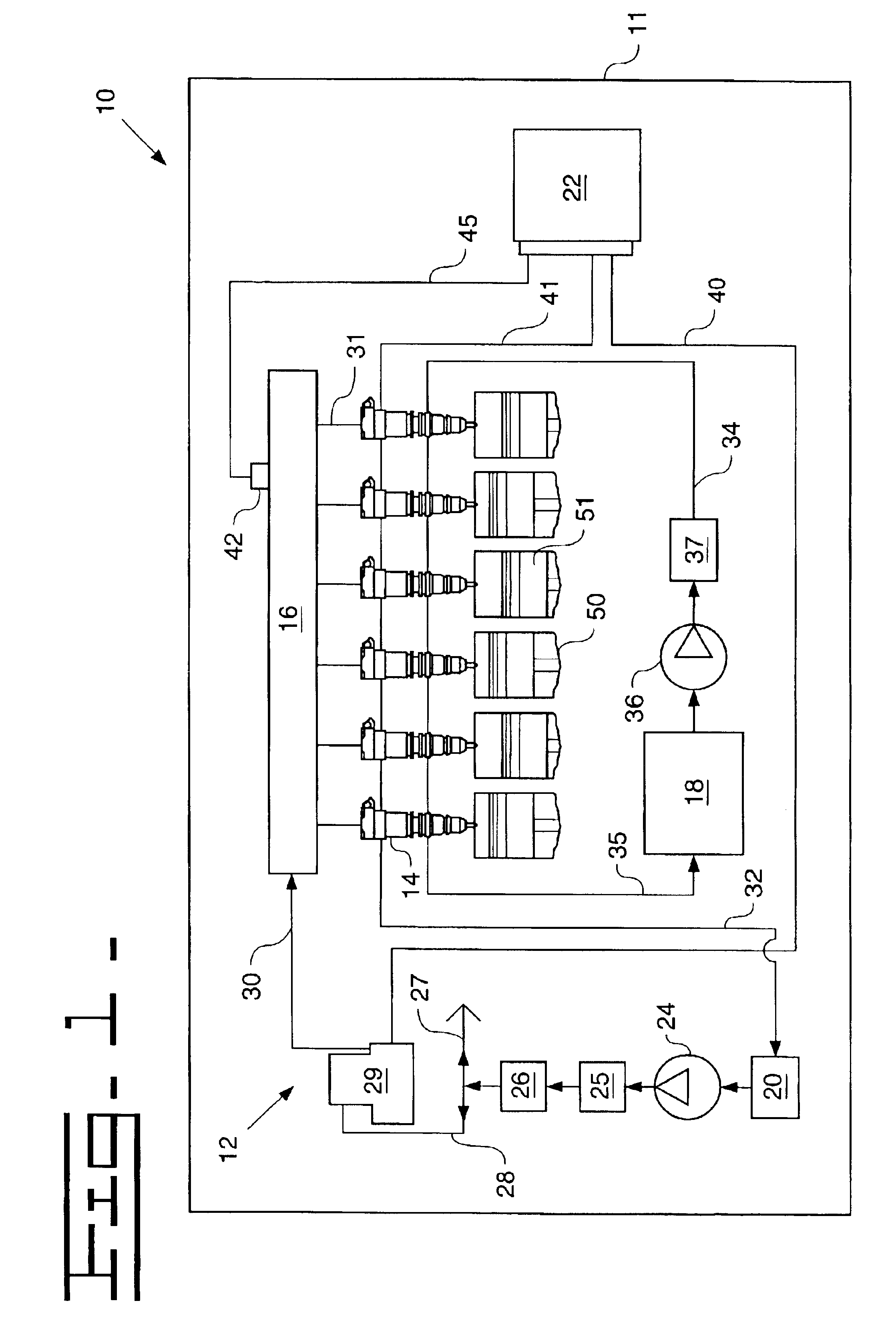
Referring to FIG. 1, there is shown a schematic representation of an engine 10 according to the present invention. A six cylinder diesel engine 10 includes an engine housing 11 and a common rail fuel injection system 12. The system 12 includes an individual fuel injector 14 for each engine cylinder 50, a single common rail 16, an oil sump 20 fluidly connected to the common rail 16, and a fuel tank 18 on a separate fluid circuit. Those skilled in the art will appreciate that in other applications there may be two or more separate common rails, such as a separate rail for each side of a V8 engine. An electronic control module 22 controls the operation of fuel injection system 12. The electronic control module 22 preferably utilizes advanced strategies to improve accuracy and consistency among the fuel injectors 14 as well as pressure control in common rail 16. For instance, the electronic control module 22 might employ electronic trimming strategies individualized to each fuel injecto...


PUM


Abstract

A method for operating an engine at idle that reduces NOx and controls smoke and hydrocarbon emissions. An idle delivery quantity of fuel is determined and divided into a first quantity of fuel and a second quantity of fuel in approximately equal quantities. During a compression stroke of an engine piston, the first quantity of fuel is injected into an engine cylinder. Adjusting at least one of timing and quantity of the injection of the first quantity of fuel reduces, at least in part, NOx emissions. At a timing angle of at least thirty degrees after the first quantity of fuel is injected and after the first quantity of fuel has been burned, there is an injection of the second quantity of fuel. Adjusting at least one of timing and quantity of the injection of the second quantity of fuel reduces, at least in part, smoke emissions.

Description

TECHNICAL FIELDThe present invention relates generally to diesel engines, and more particularly, a method for reducing undesirable emissions from diesel engines operating at idle.BACKGROUNDEngineers are constantly seeking ways to reduce undesirable engine emissions without over reliance upon exhaust after treatment techniques. One strategy is to seek ways to improve performance of fuel injection systems at idle. Over the years, engineers have come to learn that engine emissions can be a significant function of the timing, the number, and the quantity of fuel injections. However, engineers have often found that adjustments in the fuel injection system that result in a reduction of NOx emissions may result in an increase of hydrocarbon and particulate emissions, and vice versa.For instance, fuel injection systems such as that shown in co-owned U.S. Pat. No. 5,492,098 issued to Hafner et al. on Feb. 20, 1996 use a split fuel injection near top dead center of the engine piston's compres...

Claims


Application Information

Patent Timeline
IPC IPC(8): F02B3/00F02B3/12F02M45/02F02M45/00F02D41/14F02D41/40
CPCF02B3/12F02D41/402F02M45/02F02D41/146F01N2430/085Y02T10/44Y02T10/40
Inventor RASMUSSEN, JASON J.DUFFY, KEVIN P.BEST, KURTIS M.ROTH, MATTHEW R.
Owner CATERPILLAR INC
Learn More