
High-pressure sealing element to four injectors

a sealing element and high-pressure technology, applied in the direction of fluid pressure injection control, fuel injection apparatus, charge feed system, etc., can solve the problems of production effort and expense, and achieve the effect of simple production

Inactive Publication Date: 2005-01-25
ROBERT BOSCH GMBH
View PDF7 Cites 8 Cited by
  • Summary
  • Abstract
  • Description
  • Claims
  • Application Information

AI Technical Summary

Benefits of technology

The invention provides a sealing element for a fuel injector that can be easily assembled and offers a reliable sealing performance even at high pressures. The sealing element is made from metal and is securely fitted onto an insert part using a press fit. This design prevents deformation of the sealing element and ensures a tight seal between the insert part and a valve component. The sealing element is a symmetrical part that can be produced economically. Overall, the invention simplifies assembly and ensures a reliable sealing performance even at high pressures, which is important for fuel injection systems.

Problems solved by technology

Moreover, in the embodiment until now, with the use of the bronze-reinforced teflon ring and the metal support ring, it is necessary that these rings be mounted at the correct position by a secure process, which necessitates considerable effort and expense in production.

Method used


Image

  • High-pressure sealing element to four injectors
  • High-pressure sealing element to four injectors
  • High-pressure sealing element to four injectors

Examples


Embodiment Construction

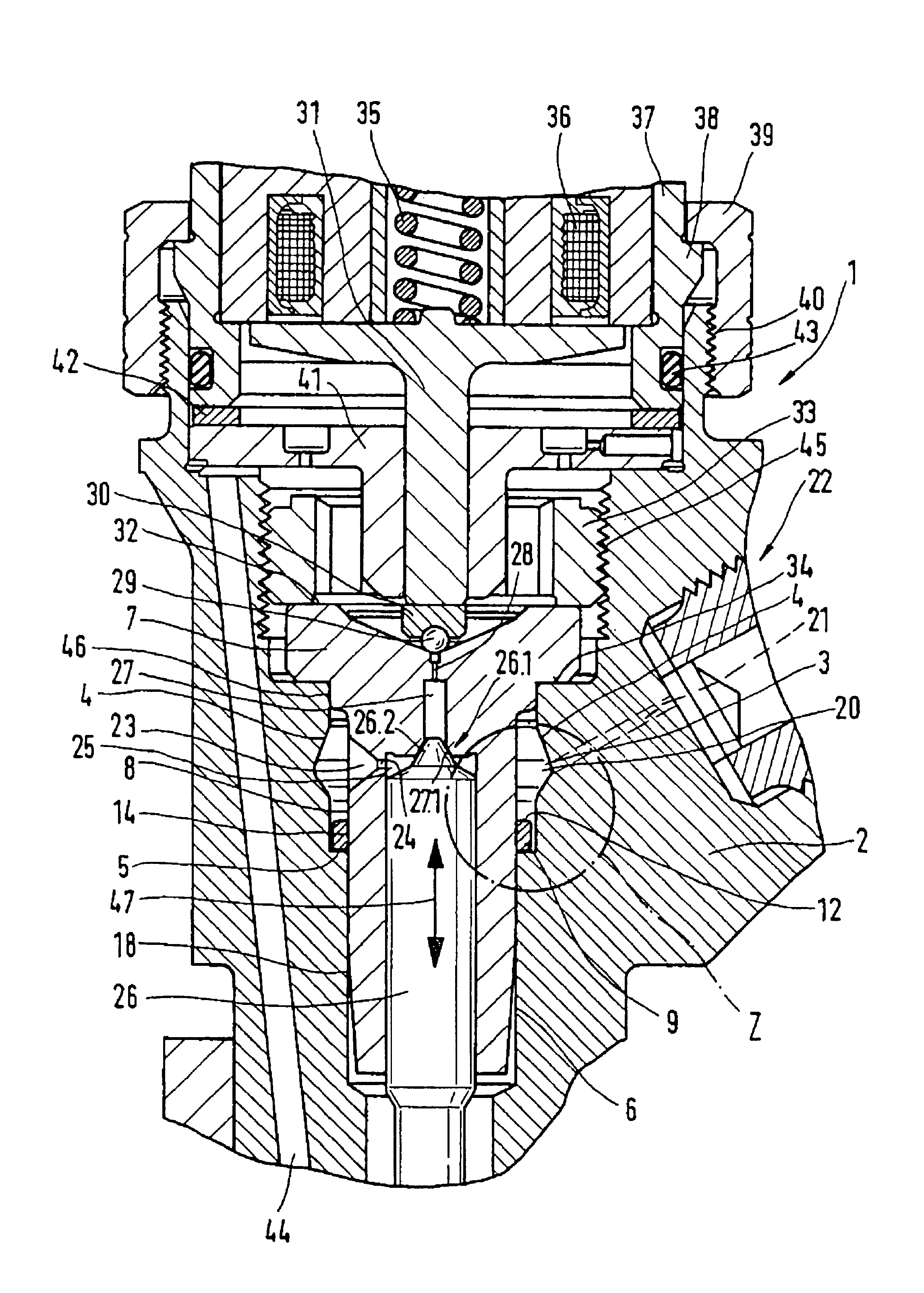
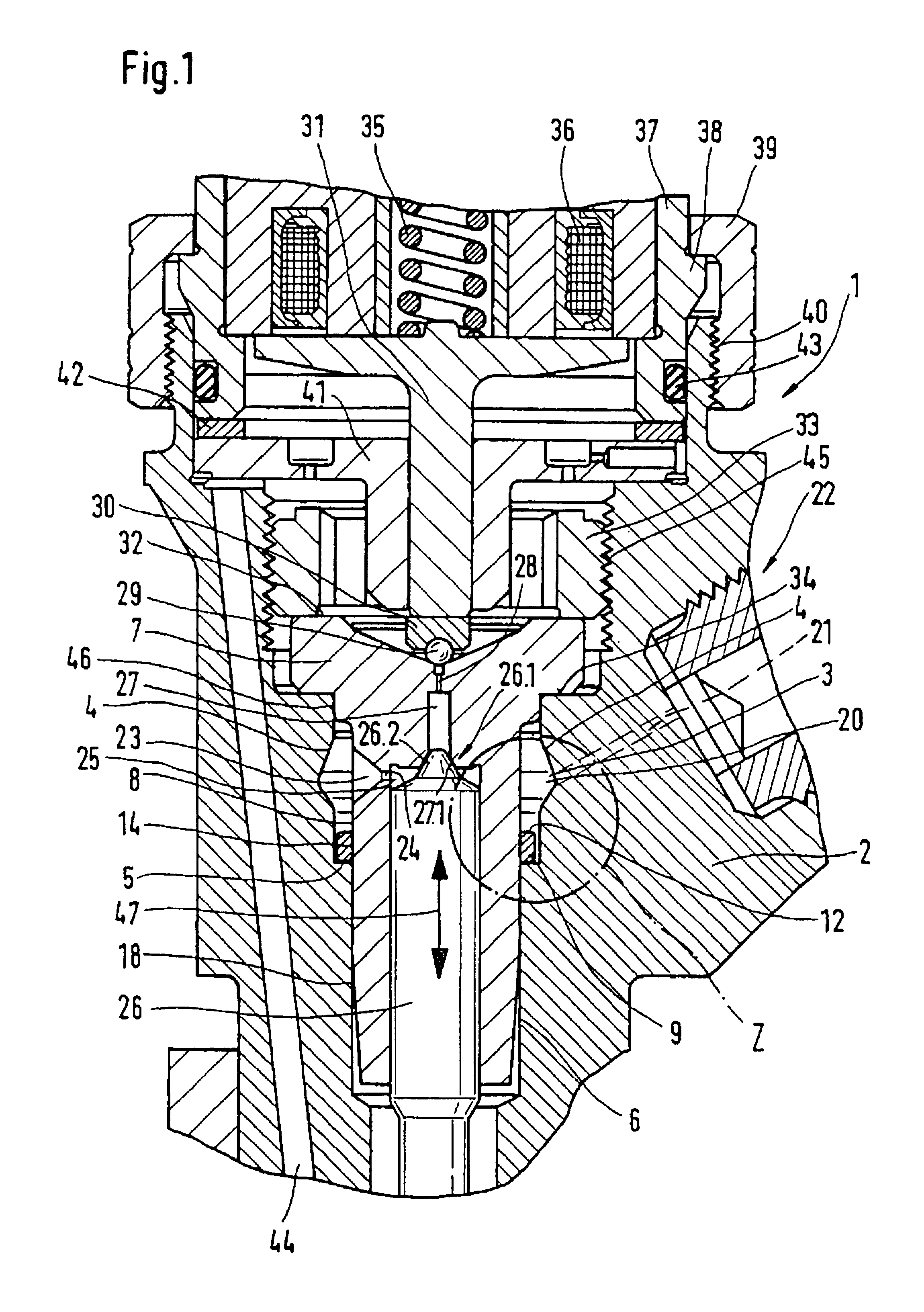
FIG. 1 shows a longitudinal section through the components of a fuel injector and of the injector housing.

From the view in FIG. 1 it can be seen that a fuel injector 1 used in a fuel injection system for injecting fuel includes an injector housing 2. The injector housing 2 contains a pressure chamber 3, from whose bottom 5 a bore 6 extends through the injector housing 2. The bore 6 is penetrated by a rotationally symmetrically embodied insert part 7. The insert part 7 can change over, in the course of its axial length, from a cylindrical cross section to a frustoconically tapered section. Between the circumference 8 of the insert part 7 and the wall of the bore 6 is an annular gap 18, which is required for reasons of assembly. An injection valve member 26, embodied for instance as a valve piston shown in FIG. 1, is received inside the insert part 7 and as represented by the double arrow 47 in FIG. 1 executes a vertical stroke motion for opening / closing injection openings, not shown ...


PUM


Abstract

An injector for injecting fuel into the combustion chamber of an internal combustion engine includes an injector housing, in which a pressure chamber surrounds an insert part. The pressure chamber can be filled with fuel at high pressure via a high-pressure inlet. Via the pressure chamber, a control chamber defined by the insert part and a valve component is subjected to pressure. The valve component is movable inside the insert part, thus executing a stroke motion. A one-piece, metal sealing element is received by a nonpositive connection on the circumference of the insert part is subjected to the high pressure prevailing in the pressure chamber.

Description

BACKGROUND OF THE INVENTION1. Field of the InventionIn fuel injection systems for air-compression internal combustion engines, injection systems with a common rail are presently used. These fuel injection systems also include injectors for injecting fuel into the combustion chambers of the engine, and in terms of tightness and material strength these must withstand the pressures prevailing in the fuel injection system. To that end, annular sealing elements are used on injectors, with which sealing off of the high-pressure region of the injector from regions of low pressure of the injector is performed. If the pressure level in fuel injection systems is raised for the sake of greater thermodynamic efficiency of the engine, then the demands made of the sealing elements of the fuel injector also become more stringent.2. Prior ArtGerman Patent Disclosure DE 196 19 523 A1 relates to a fuel injection valve for high-pressure injection. In this embodiment, a fuel injection valve is proposed...

Claims


Application Information

Patent Timeline
Patent Type & Authority Patents(United States)
IPC IPC(8): F02M61/00F02M61/16F02M47/02F02M47/00
CPCF02M47/027F02M61/16F02M2547/003F02M2200/16
Inventor RUTHARDT, SIEGFRIEDBAUER, TIBORBALLERSTEDT, WOFGANG
Owner ROBERT BOSCH GMBH
Learn More