Valve for dispensing two liquids at a predetermined ratio

a technology for beverage dispensing valves and valves, which is applied in the direction of liquid transferring devices, transportation and packaging, mechanical equipment, etc., can solve the problems of improper ratio of drinks, mechanical complexity, and negative effects on retailers as well as drink brand owners, and achieve accurate sense of flow rate variations, low cost, and not easy to damag

Inactive Publication Date: 2005-01-25
IMI VISION LTD
View PDF2 Cites 48 Cited by
  • Summary
  • Abstract
  • Description
  • Claims
  • Application Information

AI Technical Summary

Benefits of technology

e and low in cost. A further major advantage of the present invention is the use of a microelectronic strain gage type differential pressure sensor approach for determining the syrup flow rate. Syrup has proven to be a difficult substance to work with owing in large part to its viscosity, the temperature sensitivity of that viscosity and that it can be corrosive and harbor the growth of microorganisms. The microelectronic sensors have been found herein to be suitable for use with beverage syrups in that they are able to accurately sense variations in the flow rate thereof without much effect as to viscosity changes, and are not degraded chemicall

Problems solved by technology

However, a failing with such systems is that they require both fluids to be held within relatively narrow flow rate windows in order to work effectively.
As is well understood, differences in ambient temperature, syrup viscosity, water pressure and the like can all conspire to affect one or both of the flow rates to a degree that the drink is ratioed improperly becoming either too dilute or too concentrated.
As a result thereof, a drink that is too sweet can waste syrup costing the retailer money, and whether too sweet or not sufficiently so, presents the drink in less than favorable conditions, also reflecting negatively on the retailer as well as the drink brand owner.
However, these systems have met with difficulty in that there inherently exists a mechanical complexity relative to providing for inlet and outlet lines to each piston and providing for the correct timing of the opening and closing of such lines.
Such complexity increases cost

Method used


Image

  • Valve for dispensing two liquids at a predetermined ratio
  • Valve for dispensing two liquids at a predetermined ratio
  • Valve for dispensing two liquids at a predetermined ratio

Examples


Embodiment Construction

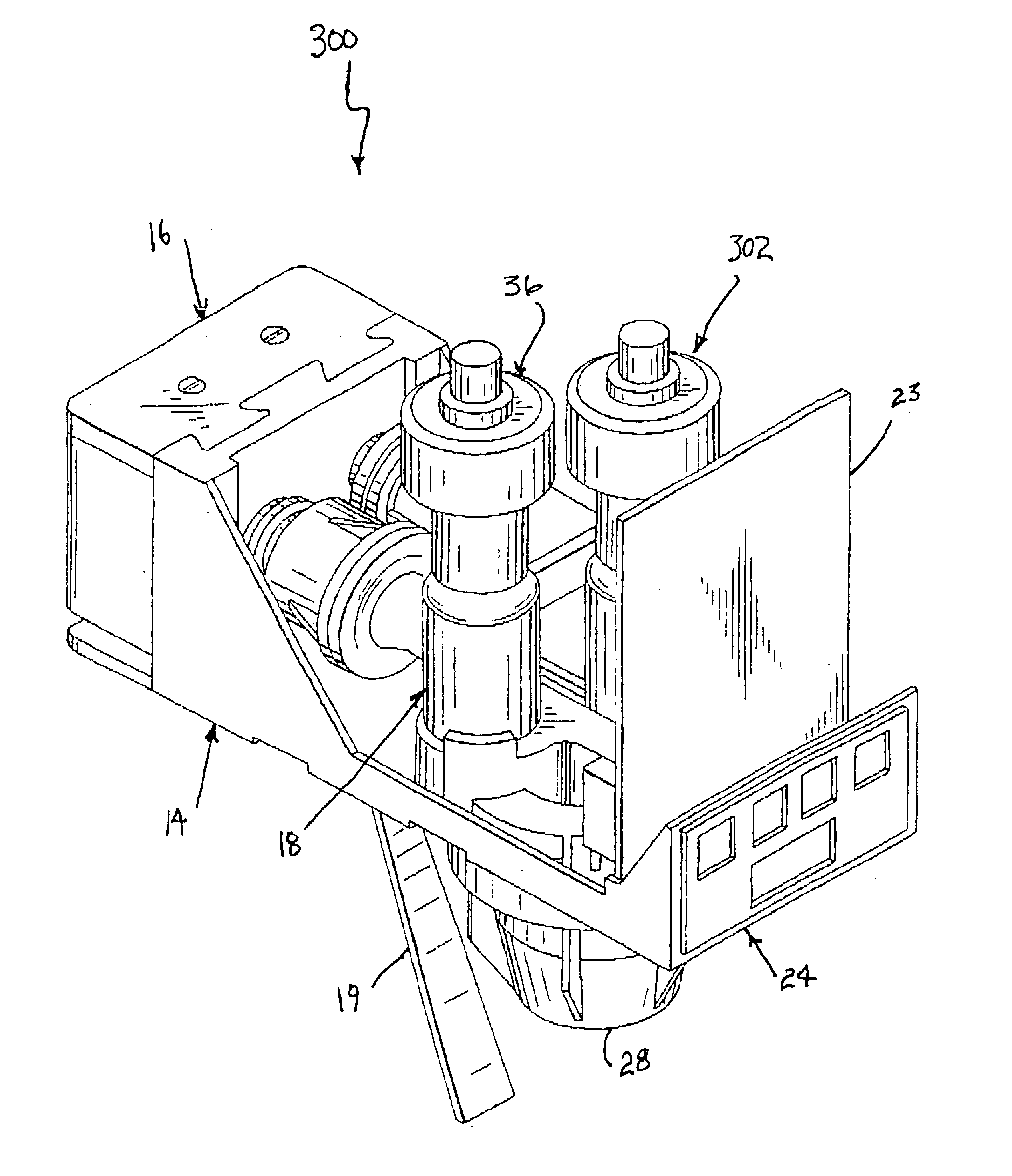
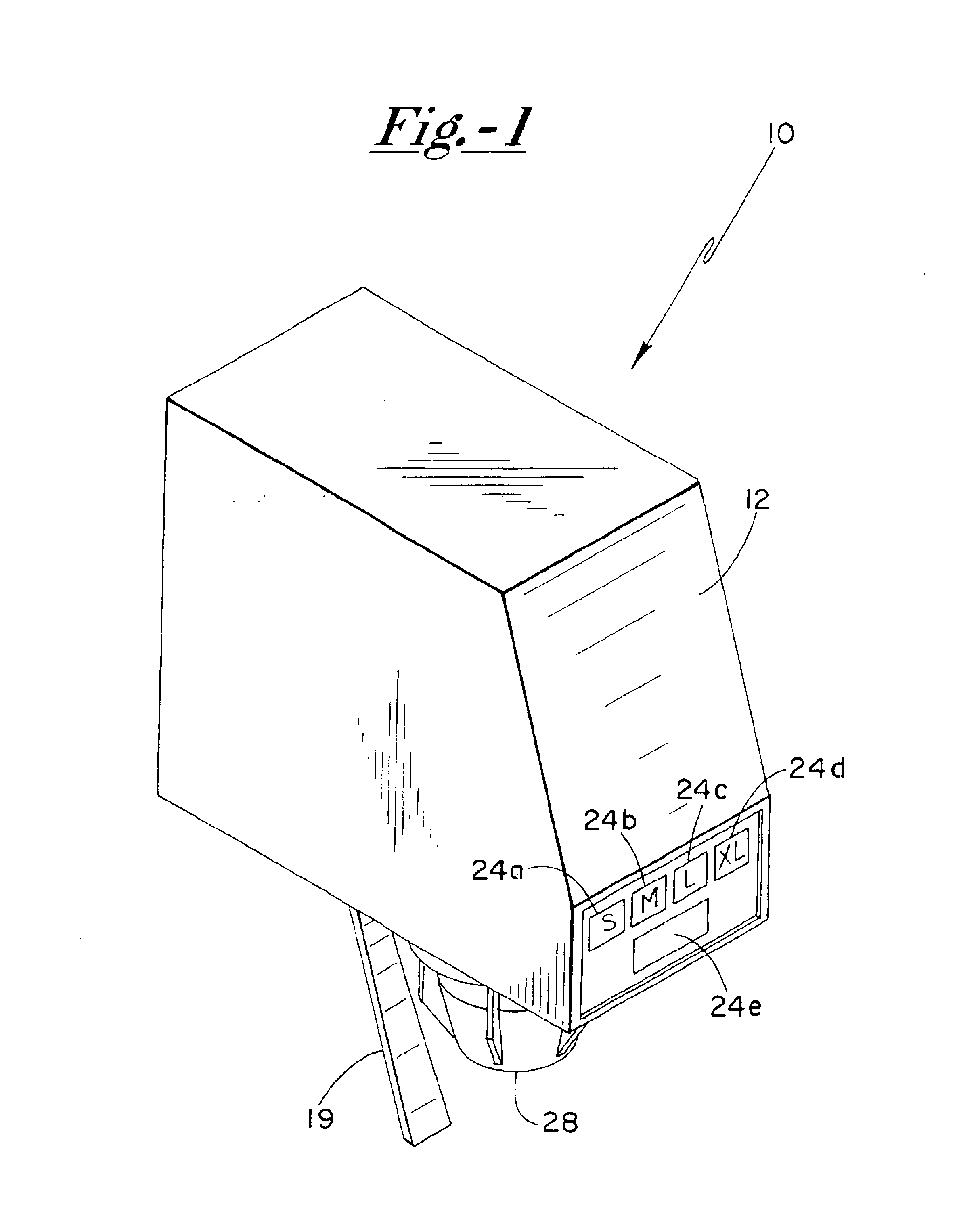
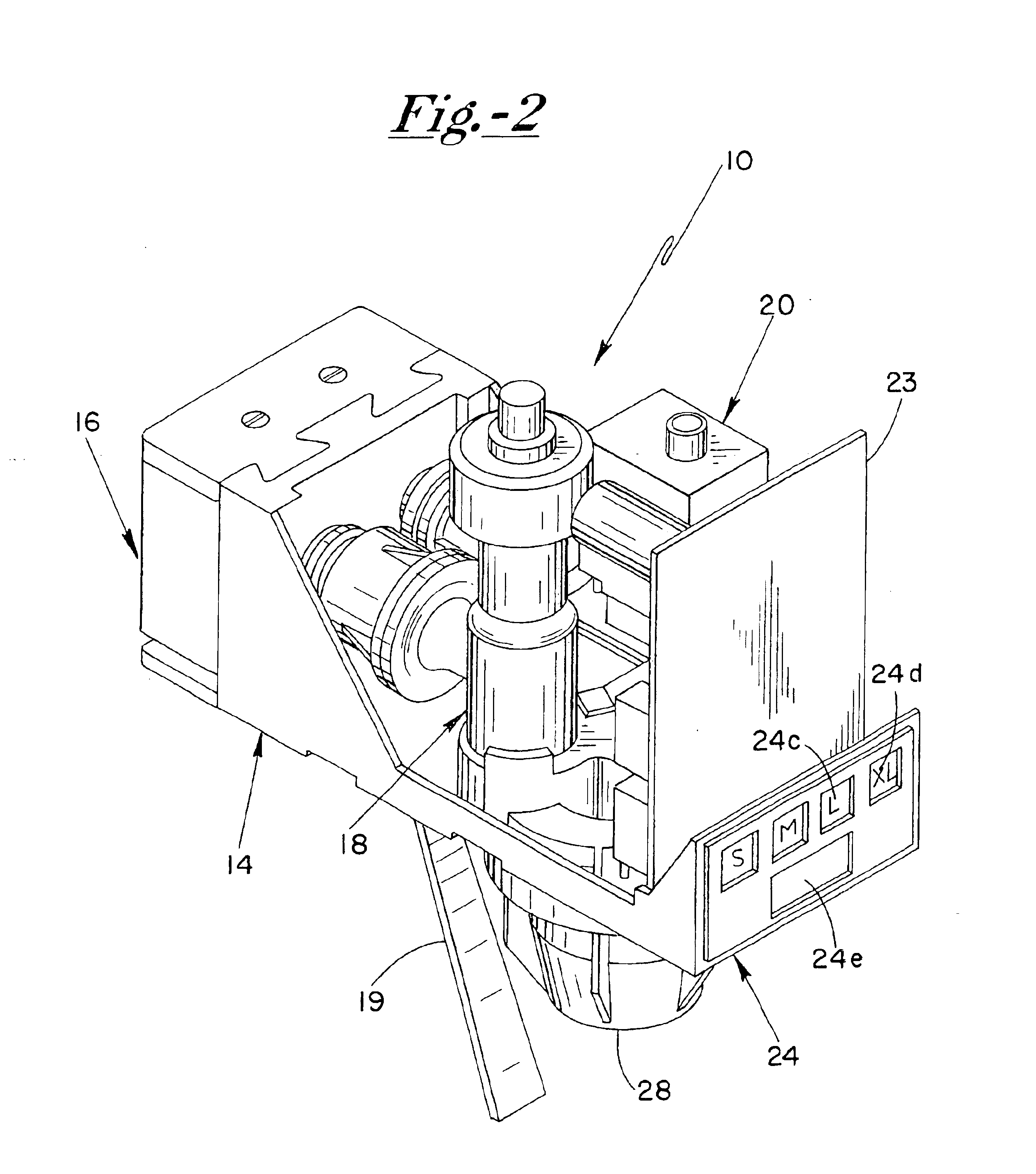
The valve of the present invention is seen in FIG. 1 and generally referred to by the numeral 10, and includes a removable outer protective shell 12. Removal of shell 12, as seen in FIGS. 2 and 3, reveals various internal valve components including a base plate 14, a quick disconnect mounting block 16, a syrup flow body assembly 18, a water flow body assembly 20, a nozzle body assembly 22 and a printed circuit board electronic control 23. Base plate 14 includes a front push button control portion 24 having a plurality of diaphragm type switches 24a-24e for operating valve 10. Switch 24e causes valve 10 to dispense for as long as it is operated / pushed. In the same manner, a lever arm 19 can alternatively be used to operate a switch, not shown, to cause valve 10 to dispense. As is well understood, arm 19 is pivotally suspended from base plate 14 and is typically actuated by pushing a cup to be filled there against followed by retraction of the cup once it is filled. Switches 24a-e are...


PUM


Abstract

A post-mix beverage valve provides for automatic, accurate beverage ratioing. A valve body can be assembled, and includes a water flow hard body, syrup body and common nozzle body. The water and syrup flow bodies define flow channels and include one end for connection to water and syrup respectively, and opposite ends for fluid connection to the nozzle body. The water flow channel includes a turbine flow sensor connected to a micro-controller determining the water flow rate. The syrup flow channel includes a flow sensor, two MEMS pressure sensors, monitoring the syrup. The sensors are connected to the micro-controller and positioned about an orifice and senses sense a differential pressure indicative of syrup flow rate solenoid regulates flow of syrup through the syrup body. A stepper motor on the water body controls a rod in the flow channel in conjunction with a v-groove.

Description

FIELD OF THE INVENTIONThe present invention relates generally to post-mix beverage dispensing valves and in particular to such valves having active ratio control apparatus.BACKGROUNDPost-mix beverage dispensing valves are well known in the art and are typically used to mix together two beverage constituents at a desired ratio to produce and dispense a finished drink. Such constituents generally consist of a concentrated syrup flavoring and a diluent comprising carbonated or uncarbontaed water. Various control strategies have been employed to maintain the desired syrup to water ratio. “Piston” type flow regulators are a well known purely mechanical system that employ spring tensioning of pistons that constantly adjust the size of orifice flow openings to maintain the desired ratio between the fluids. However, a failing with such systems is that they require both fluids to be held within relatively narrow flow rate windows in order to work effectively. As is well understood, differenc...

Claims


Application Information

Patent Timeline
IPC IPC(8): B67D1/12B67D1/14B67D1/00F16K5/00F16K5/10F16K5/04B67D7/74
CPCB67D1/005B67D1/0085B67D1/1218B67D1/1234F16K5/10B67D1/14F16K5/0414B67D1/1295B67D2001/0088F16K1/54
Inventor HENRY, PAULCZECK, STEVESIMMONS, PHILIP ANDREWHEYES, KEITH JAMESJOHNSON, MARTINATKINSON, JAMIE
Owner IMI VISION LTD
Why Eureka
Try Eureka