Dual function bailer

Inactive Publication Date: 2005-01-25
PRATT DAVID W
View PDF5 Cites 6 Cited by
  • Summary
  • Abstract
  • Description
  • Claims
  • Application Information

AI Technical Summary

Benefits of technology

The longstanding but heretofore unfulfilled need for an improved bailer that eliminates the contamination that may arise from in-the-field bailer emptying is now met by a new, useful, and nonobvious bailer construction. The novel construction includes a bailer having an elongate tubular body that has a first or upper end and a second or lower end. The second end has a one-way valved opening so that liquid fluid may flow into the elongate tubular body when the bailer is immersed in a body of liquid fluid and so that liquid fluid is substantially prevented from flowing out of the elongate tubular body when the bailer is lifted from the body of liquid fluid.
In a first embodiment, an imperforate cap is adapted to fit onto the second, lower end of the elongate tubular body. The imperforate cap prevents liquid fluid from flowing out of the second end of the elongate tubular body independently of the position of the bailer.
An imperforate cap is also adapted to fit onto the first, uppermost end of the elongate tubular body. The imperforate cap prevents liquid fluid from flowing out of the first end of the elongate tubular body independently of the position of the bailer. A smaller in diameter cap is used at the uppermost end of the bailer in those bailer designs where the top end is tapered downwardly to have a smaller diameter than the diameter of the elongate tubular body.
Where the bailer is of the type having a downspout that depends from the second end of the elongate tubular member, an alternative embodiment of the invention provides an imperforate cap adapted to fit onto the downspout. The imperforate cap prevents liquid fluid from flowing out of the downspout independently of the position of the bailer.
Accordingly, when a sample has been taken, the user need not employ a VOC device, nozzle, or other bailer-emptying device to transfer the contents of the bailer into a sample container. No device of any kind is used to empty the bailer in the field. Instead, the appropriate caps are secured to the bailer, and the bailer itself is shipped to a laboratory. Thus, the bailer serves the dual function of a bailer and as a sample container. In this way, the bailer may be emptied in a sterile laboratory free of contamination possibilities.
Yet another object is to provide a bailer that reduces contamination of a sample by eliminating any added oxygen of the type caused by pouring collected liquid fluid from the uppermost end of the bailer or by using an emptying device that empties the bailer from its lowermost end, such contamination causing incorrect sample data, i.e., producing false readings.

Problems solved by technology

This emptying procedure is unacceptable, however, because it allows oxygen to enter the liquid fluid, thereby resulting in false data.
VOC devices, nozzles, and other emptying devices also add expense to the bailer manufacturing process.
Inventors in the bailer field have developed numerous emptying devices, but the problems associated therewith persist.

Method used


Image

  • Dual function bailer
  • Dual function bailer
  • Dual function bailer

Examples


Embodiment Construction

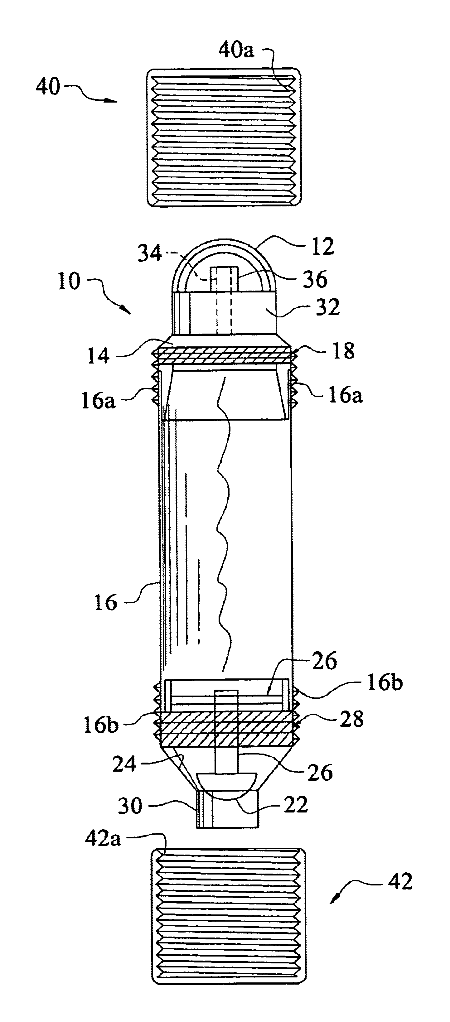
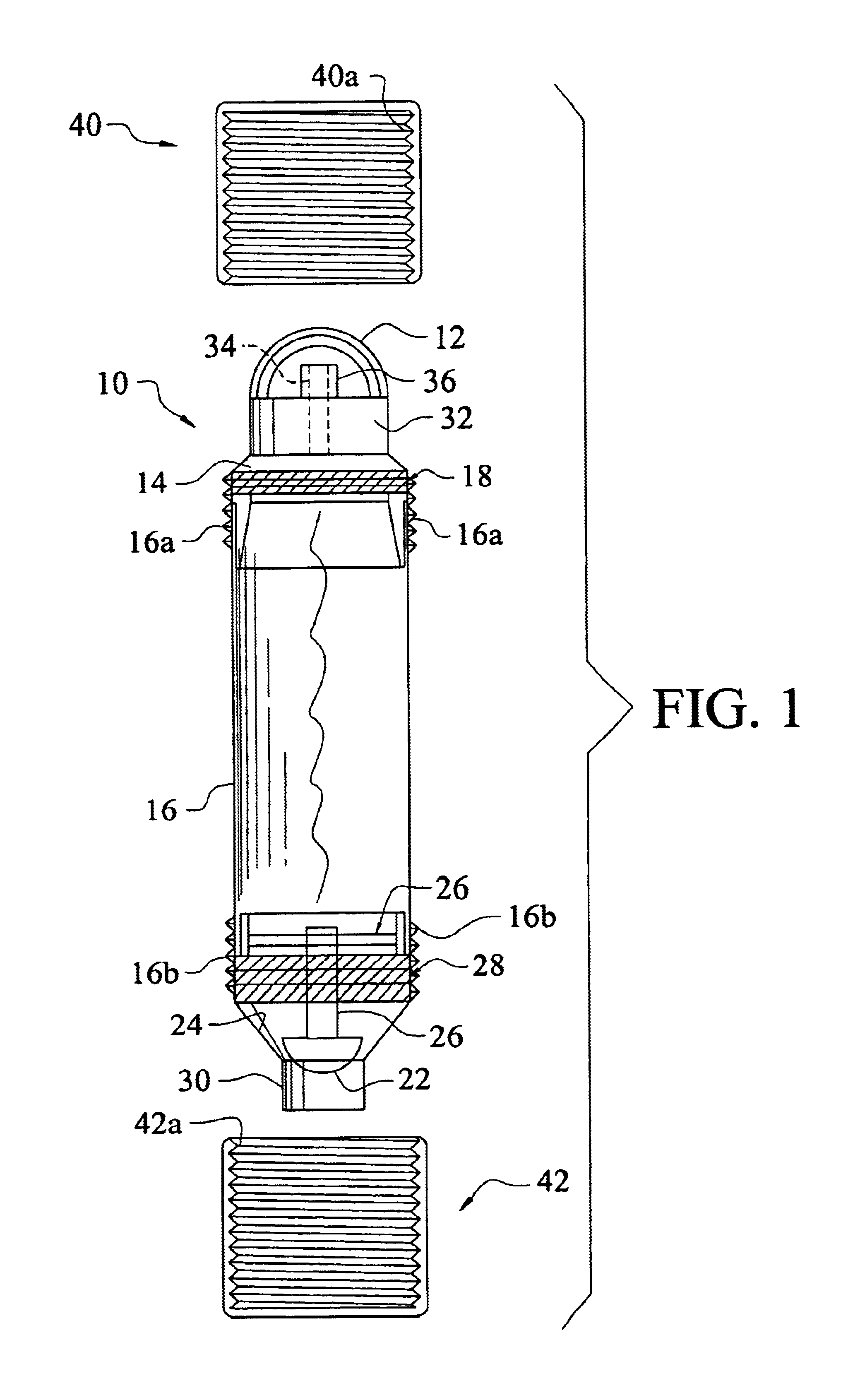
Referring to FIG. 1, it will there be seen that the reference numeral 10 denotes an illustrative embodiment of the present invention.

The invention has utility with bailers of all types. It will be described first in connection with a bailer having more features than a conventional bailer, just to make it clear that the novel structure will work with sophisticated bailers as well as common bailers having no extra features.

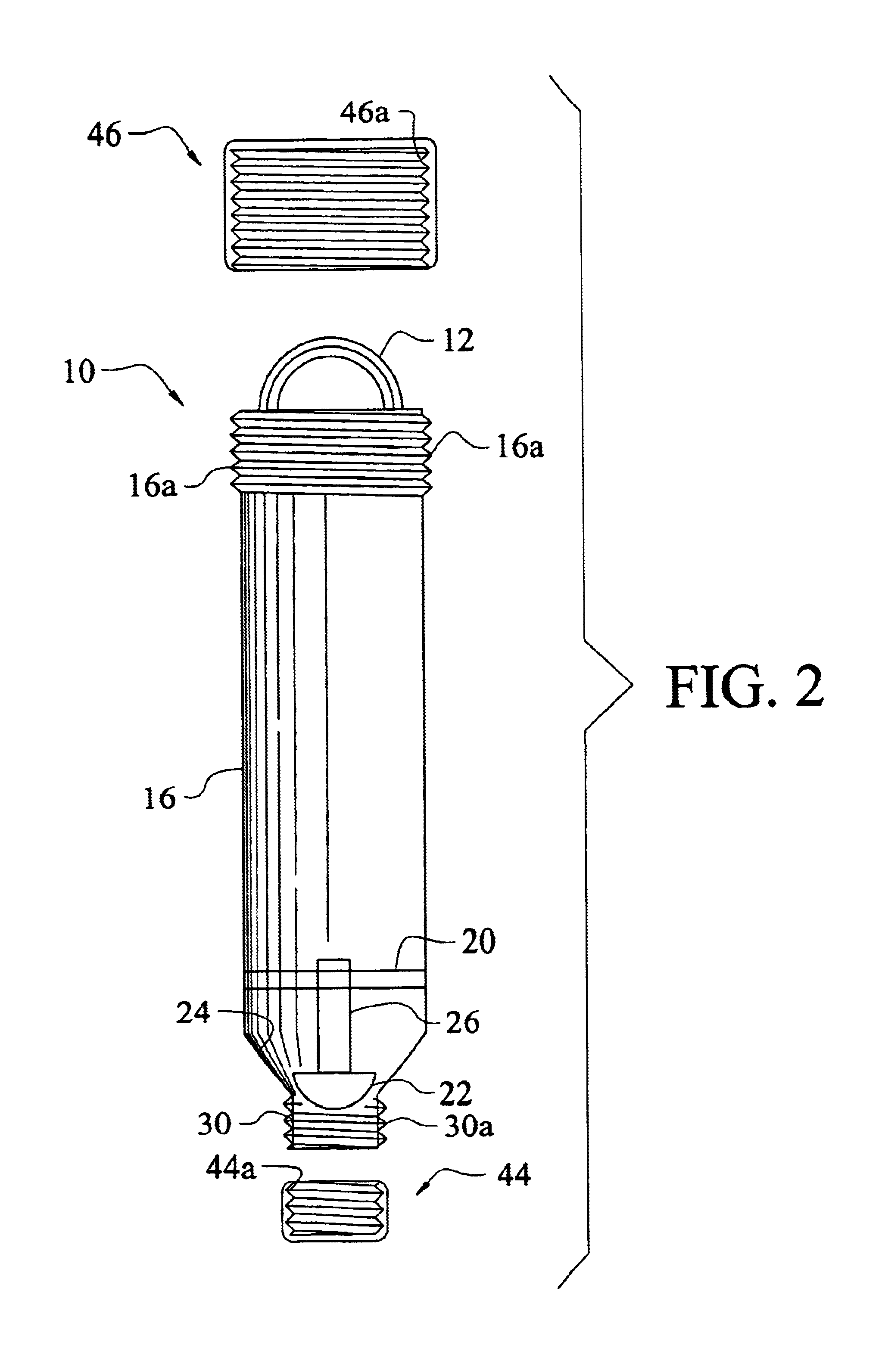
Bailer 10 includes handle 12 at its uppermost end to which is secured a rope, not shown, to enable the lowering and lifting of the bailer into and from a body of liquid fluid. In this sophisticated bailer embodiment, a weight housing 14 is slidingly received within tubular main body 16 of the bailer and provides a means for holding top weight members, collectively denoted 18.

A spider assembly 20 is positioned near the lower end of tubular main body 16 and serves to guide hemispherical valve body or check ball 22 as it rises and falls with respect to valve seat 24. V...


PUM


Abstract

An upper imperforate cap closes the uppermost end of a bailer and a lower imperforate cap closes the lowermost end of the bailer. In a preferred embodiment, screwthreads are formed in the uppermost and lowermost ends of the bailer and complemental screwthreads are formed in the upper and lower caps. In another embodiment, screwthreads are formed in a downspout and complemental screwthreads are formed in an imperforate downspout cap. By capping the opposite ends of a bailer, the bailer serves as its own container when the sample contained within it is shipped to a laboratory. This eliminates VOC devices, nozzles, and the concomitant contamination that may result from emptying a bailer in the field.

Description

BACKGROUND OF INVENTION1. Field of the InventionThis invention relates, generally, to bailers. More particularly, it relates to a bailer that performs the function of a bailer and of a sample container.2. Description of the Prior ArtAll conventional bailers require emptying into a sample container shortly after a sample has been taken from a body of water or other liquid fluid. The sample container is then placed in a cooler and transported to a lab so that the sample can be analyzed.Most workers in the field simply invert the bailer to empty it. This emptying procedure is unacceptable, however, because it allows oxygen to enter the liquid fluid, thereby resulting in false data. Moreover, the pouring action agitates the liquid fluid.To encourage workers in the field to empty bailers without inverting them, numerous emptying devices have been developed that lift the valve at the lowermost end of the bailer from its valve seat. The most common emptying device is a nozzle; another well...

Claims


Application Information

Patent Timeline
IPC IPC(8): G01N1/12G01N33/18
CPCG01N1/12G01N33/18
Inventor PRATT, DAVID W.
Owner PRATT DAVID W
Why Eureka
Try Eureka