
Titanium Powder Production Apparatus and Method

Active Publication Date: 2013-09-12
FMW COMPOSITE SYST +1
View PDF5 Cites 2 Cited by
  • Summary
  • Abstract
  • Description
  • Claims
  • Application Information

AI Technical Summary

Benefits of technology

The patent aims to prevent powder metal contamination by using a non-contaminating metal to line the flow path or fabricating it beyond the atomization stage. The technical effect of this invention is the elimination of powder metal contamination.

Problems solved by technology

These droplets react with stainless steel producing low-melting point compounds that are brittle in nature.
These compounds enter into the titanium powder stream as contaminants and remain undetected in standard quality control techniques.
Components made out of these contaminated powders experience catastrophic in-service failures.

Method used


Image

  • Titanium Powder Production Apparatus and Method
  • Titanium Powder Production Apparatus and Method

Examples


Embodiment Construction

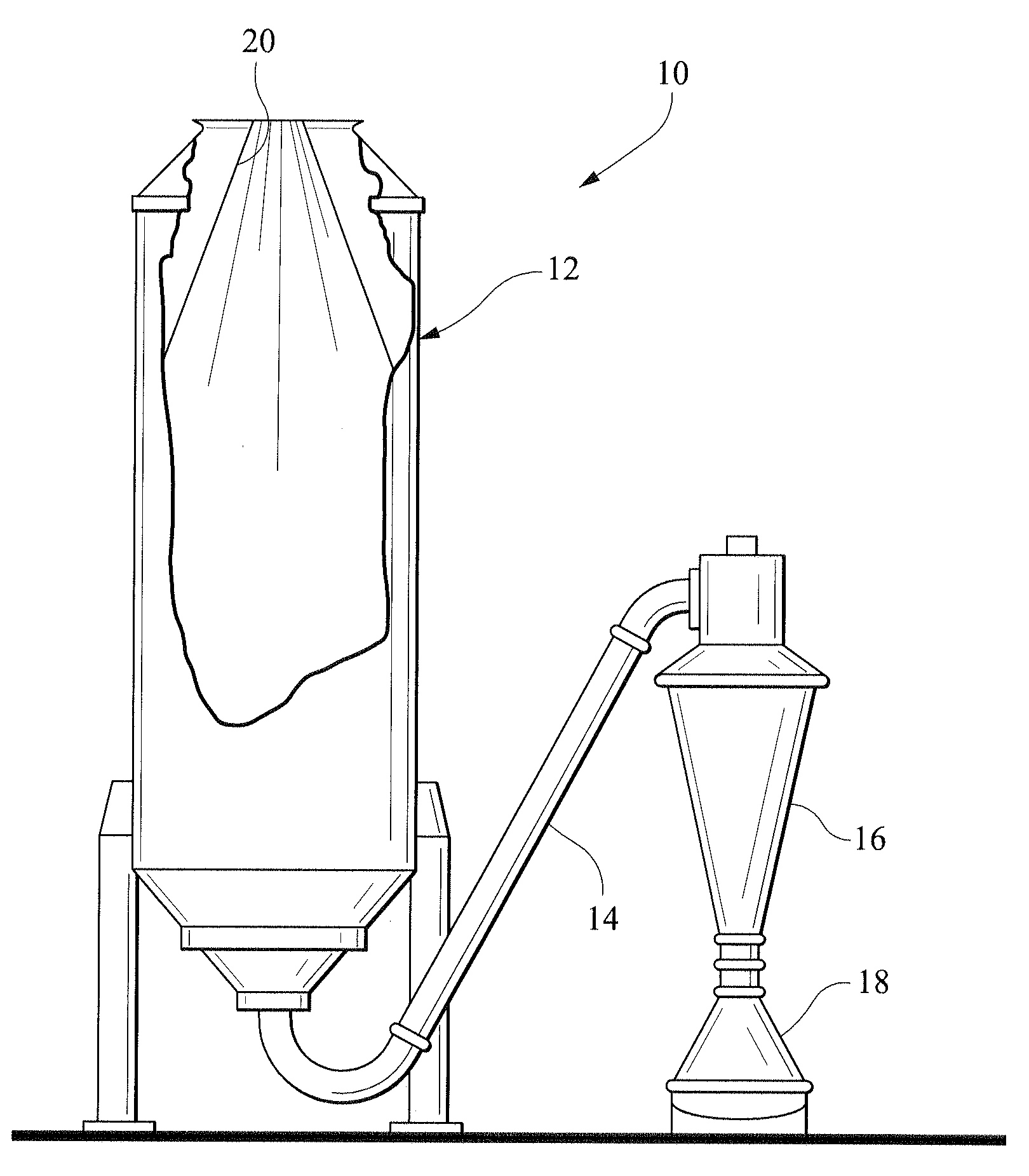
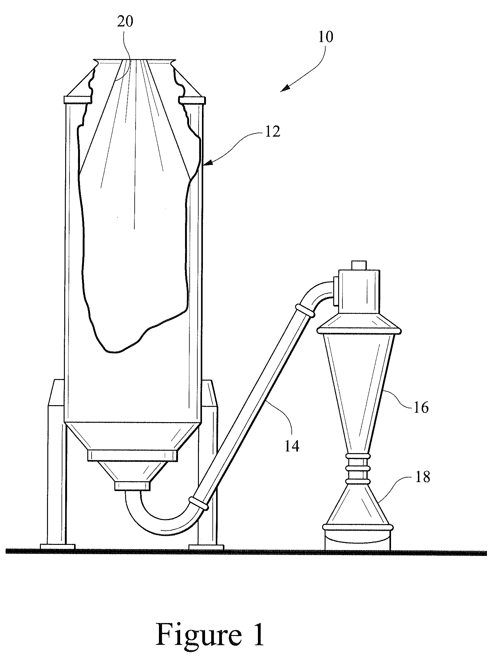
[0015]Referring to FIG. 1, apparatus 10 for producing titanium powder includes an atomization or hot spray chamber 12 for receiving an atomized liquid metal stream supply from a known system such as a cold wall induction guiding system, an electrode induction melting gas atomization process, a plasma-melting induction-guiding gas atomization method, a triple melt process or any other known system. The powder from the atomization chamber 12 is passed through a conveying tube 14, through a cyclone separator 16 and then into powder containers 18, as shown in FIG. 1.

[0016]In accordance with the present invention, the entire inside surface 20 of the atomization chamber 12 is coated with or formed of CP-Ti to prevent contamination of titanium metal powder being produced from a melt including titanium powder metal as hereinbefore described. As an illustrative example, a coating of CP-Ti on the inner surface 20 of the atomization chamber 12 may have a thickness of about 2 mm. The atomizatio...


PUM

PropertyMeasurementUnit
Thicknessaaaaaaaaaa
Lengthaaaaaaaaaa
Velocityaaaaaaaaaa

Abstract

A method and apparatus for producing titanium metal powder from a melt. The apparatus includes an atomization chamber having an inner wall that is coated with or formed entirely of CP-Ti to prevent contamination of titanium metal powder therein. The inner surfaces of all components of the apparatus in a flow path following the atomization chamber may also be coated with or formed entirely of CP-Ti.

Description

BACKGROUND OF THE INVENTION[0001]1. Field of the Invention[0002]The present invention relates to a titanium powder production apparatus and method and, more particularly, to such an apparatus and method that prevents contamination of the titanium powder.[0003]2. Description of the Background Art[0004]Powder metallurgy is an important technology in the production of parts made out of titanium for critical applications such as aerospace. Titanium metal powder is the basic raw material in this process path. Atomization using an inert gas such as argon is a commonly used process to produce uniform spherical-shaped powders that possess high packing densities. A typical device for gas atomization consists of a liquid metal stream supply source, the atomizing gas jet, and a cooling chamber. The free-falling stream of molten titanium is impinged with inert gas jet at a high velocity, the atomized droplets of titanium solidify in flight through the chamber, and are collected at the bottom of...

Claims


Application Information

Patent Timeline
IPC IPC(8): B22F9/06
CPCB22F2999/00B22F9/082B22F2009/0888B22F3/003B22F9/08B22F2009/0892
Inventor HANUSIAK, WILLIAM M.MCBRIDE, DALE R.
Owner FMW COMPOSITE SYST
Learn More