Pump with an electrodynamically supported impeller and a hydrodynamic bearing between the impeller and the stator

a technology of hydrodynamic bearing and electrodynamic support, which is applied in the direction of positive displacement liquid engine, piston pump, liquid fuel engine, etc., can solve the problems of affecting the life expectancy of bearings, mechanical contact bearings supporting the impeller are also prone to failure, and the seal of the shaft is prone to failur

Inactive Publication Date: 2005-01-25
DAVIS WILLIAM D +1
View PDF29 Cites 98 Cited by
  • Summary
  • Abstract
  • Description
  • Claims
  • Application Information

AI Technical Summary

Problems solved by technology

Shaft seals are prone to failure due to continuous mechanical wear during operation of the pump.
Mechanical contact bearings supporting the impeller are also prone to failure.
The pumped fluid may adversely affect the life expectancy of the bearings.
For example, the mechanical contact bearings and seal may be particularly susceptible to failure when in contact with caustic materials.
Alternatively, the bearings may damage the fluid being pumped.
Contact bearings, for example, may result in increased levels of hemolysis and thrombosis in blood pump applications.
One disadvantage of this design is that each magnet in a stack is constantly exposed to a significant de-magnetizing field due to the close proximity of the adjacent magnets in the stack.
Another disadvantage of this design is that the use of axially alternating magnetic rings results in a number of points of axial metastability which may create pump control or efficiency issues.
The passive magnetostatic bearings can create significant axial bearing load issues for impellers with a radial PMB.
Similarly, impellers with an axial PMB may suffer from significant radial bearing load issues.
These loading forces result in a less power efficient pump.
In contrast, an AMB will fail in the event of a power interruption, computational error, sensing error along any axis, etc.
AMB systems are thus inherently unstable.
AMB systems also require significant computational resources for position control.
The use of AMB systems introduces multiple points of failure which may be unacceptable for some pump applications (e.g., implantable pumps).

Method used


Image

  • Pump with an electrodynamically supported impeller and a hydrodynamic bearing between the impeller and the stator
  • Pump with an electrodynamically supported impeller and a hydrodynamic bearing between the impeller and the stator
  • Pump with an electrodynamically supported impeller and a hydrodynamic bearing between the impeller and the stator

Examples


Embodiment Construction

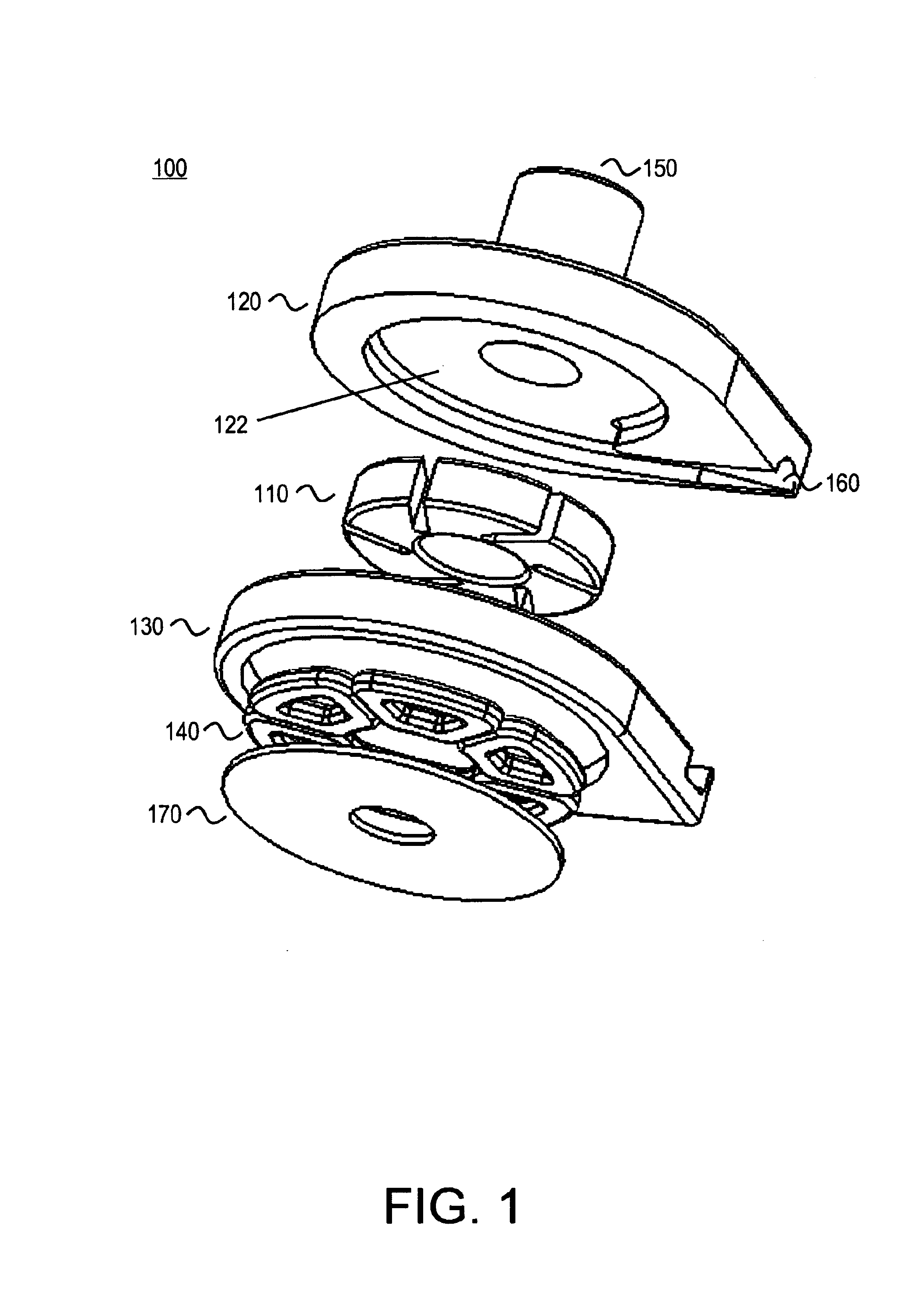
FIG. 1 illustrates one embodiment of a centrifugal pump 100 providing radial support for the impeller 110 through the use of magnetic bearings. The pump includes a top housing portion 120 and a bottom housing portion 130. When assembled the top and bottom housing portions define a volute pumping chamber 122. Rotation of impeller 110 drives the working fluid from the pump inlet 150 to the pump outlet 160.

Centrifugal pump 100 utilizes an axial flux gap motor architecture. When assembled, the top and bottom housing portions serve as a motor stator. The motor windings 140 are disposed in the stator. The impeller serves as a motor rotor and includes a plurality of permanent magnets forming motor poles. The motor poles are arranged to co-operate with the motor windings to drive the impeller and thus achieve a pumping action. Back iron 170 serves to concentrate the flux generated by the windings 140.

The pump further includes a spindle protruding from the base of the pumping chamber. The sp...


PUM


Abstract

A pump includes an impeller, a stator, and a plurality of magnets forming bearing poles coupled to a selected one of the stator or the impeller. The pump further includes a plurality of shorted coils coupled to the other of the stator and the impeller. The plurality of bearing poles and shorted coils co-operate to form an electrodynamic bearing during rotation of the impeller. The electrodynamic bearing supports the impeller either axially or radially during operation of the pump. Hydrodynamic bearing surfaces are provided for generating a hydrodynamic bearing between the impeller and stator. The plurality of magnets may comprise a plurality of distinct magnetic elements or a single element comprising a plurality of distinct magnetic domains. The plurality of distinct magnetic elements or domains may be arranged to form a Halbach array.

Description

FIELD OF THE INVENTIONThis invention relates to the field of pump design. In particular, this invention is drawn to bearings supporting pump impellers.BACKGROUND OF THE INVENTIONTraditional dynamic pumps have a pumping component and a drive component. The pumping component includes an impeller supported by mechanical contact bearings. Mechanical energy is transferred from the drive component to the impeller of the pumping component through a shaft. A shaft seal in the pumping component permits rotation of the shaft while preventing leakage around the shaft.Shaft seals are prone to failure due to continuous mechanical wear during operation of the pump. Mechanical contact bearings supporting the impeller are also prone to failure. The pumped fluid may adversely affect the life expectancy of the bearings. For example, the mechanical contact bearings and seal may be particularly susceptible to failure when in contact with caustic materials. Alternatively, the bearings may damage the flu...

Claims


Application Information

Patent Timeline
Patent Type & Authority Patents(United States)
IPC IPC(8): F04D13/06F04D29/04A61M60/178A61M60/221A61M60/232A61M60/237A61M60/422A61M60/814A61M60/822A61M60/824F04D29/048F16C39/06
CPCF04D13/0666F04D29/048A61M1/101F16C32/0436F16C2360/44F16C2316/18A61M60/824A61M60/422A61M60/148A61M60/232A61M60/237A61M60/178A61M60/814A61M60/221A61M60/822
Inventor DAVIS, WILLIAM D.LANCISI, DAVID M.
Owner DAVIS WILLIAM D
Why Eureka
Try Eureka