Method for metallurgically joining a tube to a member
a technology of metallurgy and tube, applied in the field of metalurgy, can solve the problems of long cycle time between welds, uneven quality of welds, and high cost of friction welding equipmen
- Summary
- Abstract
- Description
- Claims
- Application Information
AI Technical Summary
Benefits of technology
Problems solved by technology
Method used
Image
Examples
first embodiment
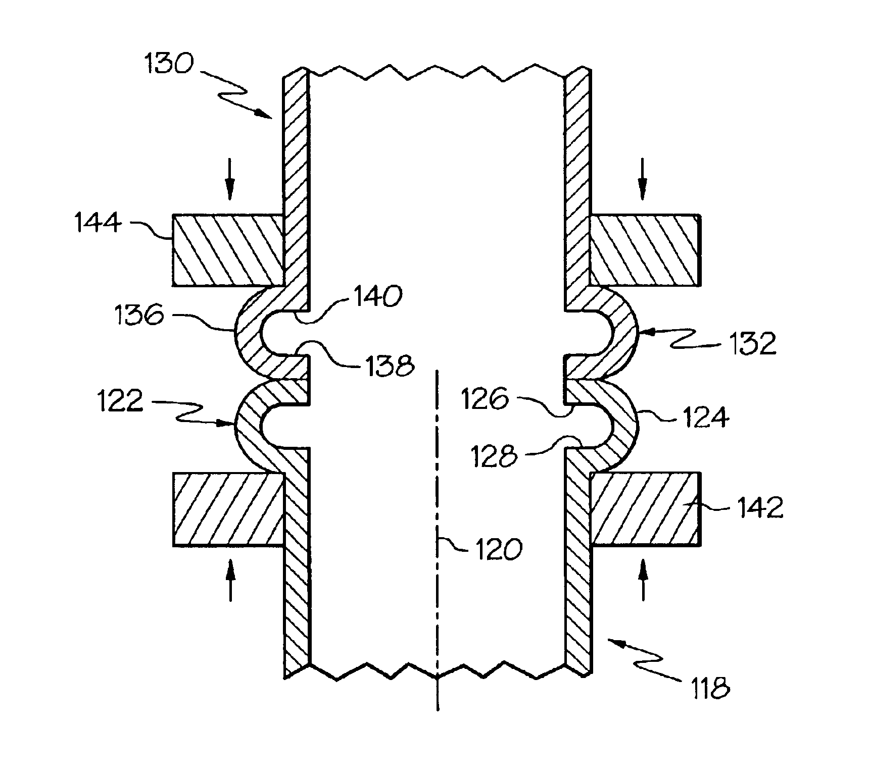
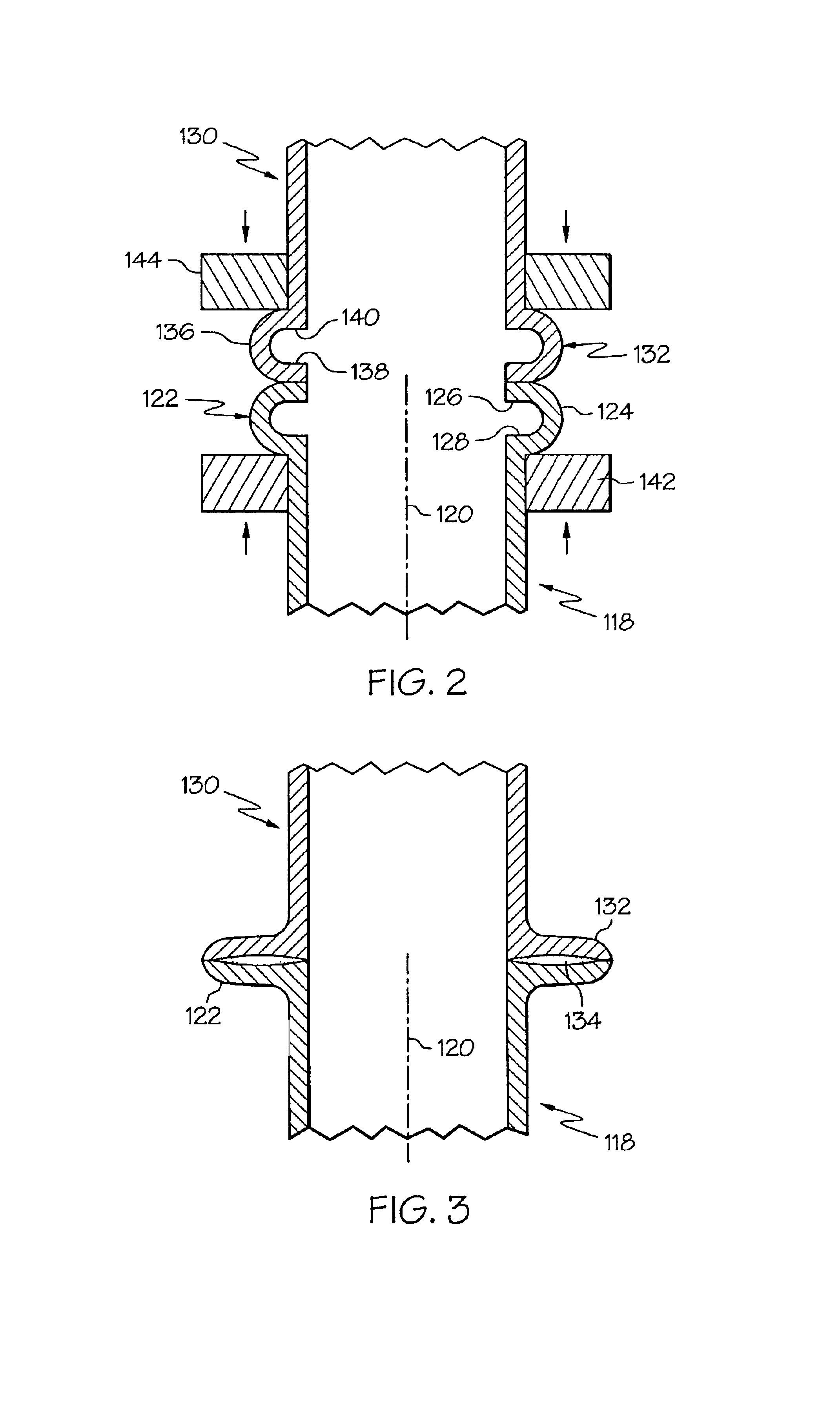
Referring to FIGS. 2-3, wherein like numerals represent like elements throughout, a second method of the invention is for metallurgically joining one tube to another tube and includes steps a) through d). Step a) includes obtaining a first tube 118 having a longitudinal axis 120 and having a first end portion 122, wherein the first end portion includes a first annular fold 124 substantially coaxially aligned with the longitudinal axis 120, and wherein the first annular fold 124 includes longitudinally-spaced-apart first and second fold portions 126 and 128. Step b) includes obtaining a second tube 130 having a second end portion 132. Step c) includes, after steps a) and b), coaxially aligning the first and second tubes 118 and 130 and disposing the first and second tubes 118 and 130 with the first end portion 122 contacting the second end portion 132. Step d) includes, after step c), creating a resistance welding current path through the first and second tubes 118 and 130 proximate ...
second embodiment
In a second example of the second method, and referring to FIG. 4, the second end portion 232 of the second tube 230 is a substantially straight end portion having a substantially-longitudinally-facing annular end 246, wherein the second tube 230 has a greater wall thickness than the first tube 218, and wherein step c) disposes the first and second tubes 218 and 230 with the annular end 246 longitudinally contacting the first annular fold 224. In one application, the second tube 230 is a nut. In one variation, the first annular fold 224 is a radially-outwardly-protruding annular fold. In one implementation, step d) uses an annular resistance-welding first electrode 242 longitudinally contacting the first annular fold 224 and uses a resistance-welding second electrode 244 disposed in radial contact with the second end portion 232. In one modification, the first electrode 242 longitudinally contacts the second electrode 244 at the completion of step d). In one arrangement, a non-elect...
third embodiment
In an alternate second example of the second method, and referring to FIG. 5, the first annular fold 324 of the first end portion 322 of the first tube 318 protrudes radially outward and longitudinally upward as shown in the figure. The first electrode 342 is disposed outside the first tube 318, and the second electrode 344 is disposed outside the second tube 330. A non-electrode first support 350 is disposed inside the first tube 318 and extends around the other end of the first tube 318, and a non-electrode second support 352 is disposed inside the second tube 330 and extends around the other end of the second tube 330. In one variation, not shown, the positions of the first electrode and the first support are interchanged, and the positions of the second electrode and the second support are interchanged.
Other embodiments for the second method are left to the artisan. Optional examples, enablements, etc. of the first method applicable to tube-to-tube joining are equally applicable...
PUM
| Property | Measurement | Unit |
|---|---|---|
| Thickness | aaaaa | aaaaa |
| Area | aaaaa | aaaaa |
Abstract
Description
Claims
Application Information
 - R&D
- Intellectual Property
- Life Sciences
- Materials
- Tech Scout
- Unparalleled Data Quality
- Higher Quality Content
- 60% Fewer Hallucinations
Browse by: Latest US Patents, China's latest patents, Technical Efficacy Thesaurus, Application Domain, Technology Topic, Popular Technical Reports.
© 2025 PatSnap. All rights reserved.Legal|Privacy policy|Modern Slavery Act Transparency Statement|Sitemap|About US| Contact US: help@patsnap.com


