Eureka AIR delivers breakthrough ideas for toughest innovation challenges, trusted by R&D personnel around the world.

Alternator field coil wire routing design

Inactive Publication Date: 2005-01-25
FORD GLOBAL TECH LLC
View PDF20 Cites 10 Cited by
  • Summary
  • Abstract
  • Description
  • Claims
  • Application Information

AI Technical Summary

Benefits of technology

The present invention overcomes the disadvantages of the prior art alternators by providing an improved alternator rotor for use in a motor vehicle. The alternator includes a stator having a stator winding, a rotor assembly positioned concentrically relative to the stator, and includes at least one pole having an outer surface. The outer surface has a radially extending groove and includes a field coil dispose

Problems solved by technology

One well known challenge with the Lundel rotor design is to create a durable method for routing the start and end leads of the field coil.
More specifically, the integrity of the attachment of the field coil leads is compromised at high alternator speeds, such as speeds greater than 25000 rpms.
While prior art methods for creating field coil lead routings have achieved their intended purpose and perform adequately at lower rpms (20,000 rpm) current routing schemes may not perform adequately at higher rpms.
Unfortunately, this method requires excessive packaging space and doesn't provide adequate field coil lead retention at high rotor speeds.

Method used


Image

  • Alternator field coil wire routing design
  • Alternator field coil wire routing design
  • Alternator field coil wire routing design

Examples


Embodiment Construction

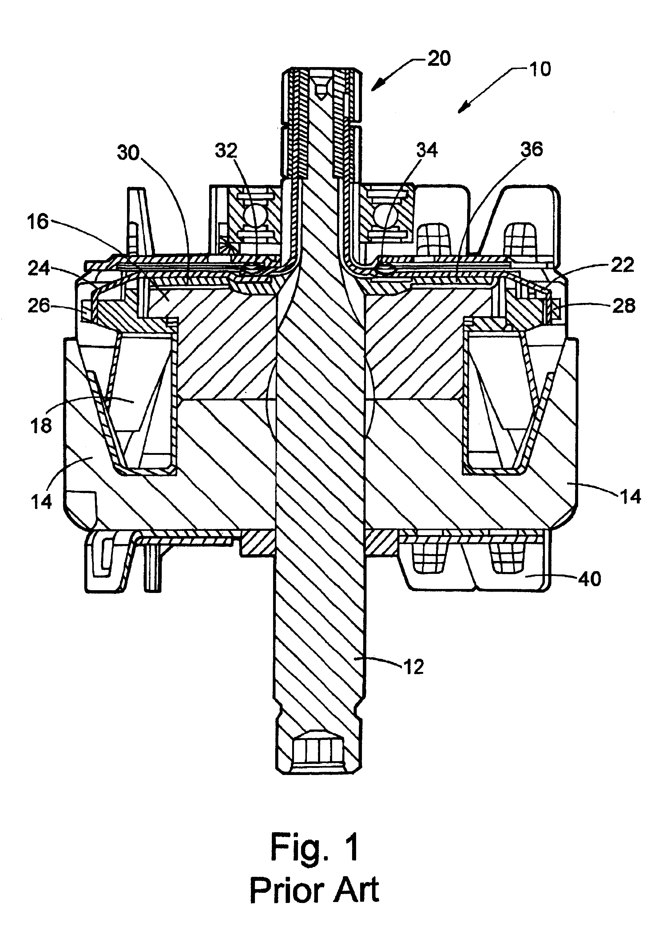
Referring now to FIG. 1, a cross-sectional view of a typical (prior art) rotor 10 for use in a Lundel style alternator (not shown) is illustrated. Rotor 10 includes a rotor shaft 12 which is mechanically coupled for rotation to a vehicle engine. A first and second claw pole 14, 16 are rigidly affixed to shaft 12 and rotatable therewith. As well known in the art, a field coil 18 wound around a bobbin (not shown) is disposed between claw poles 14 and 16. Field coil 18 cooperates with claw poles 14 and 16 to produce an electromagnetic field that results in alternating magnetic polarities on the pole fingers.

Field coil 18 is energized by an electrical current communicated to the field coil through a rotor slip ring assembly 20. More specifically, in the prior art start and end leads 22 and 24 of field coil 18 are routed from the field coil to the rotor slip ring assembly 20. As illustrated, start and end leads 22 and 24 are mechanically secured to a pair of winding posts 26 and 28 where...


PUM

PropertyMeasurementUnit
aaaaaaaaaa

Abstract

An alternator for a motor vehicle is disclosed. The alternator includes a stator having a stator winding, a rotor assembly positioned concentrically relative to the stator, and including at least one pole having an outer surface. The outer surface has a groove and includes a field coil disposed adjacent the at least one pole, the field coil having start and end leads. A slip ring is fixedly coupled to the start and end leads and a rotor shaft on which the field coil, the at least one pole and the slip ring are fixed. Moreover, the start and end leads are positioned within the groove and are retained in the groove by a locking feature formed in the outer surface of the at least one pole.

Description

TECHNICAL FIELDThe present invention relates to electric machines having stators and rotors and to methods of assembling a field coil in the rotor.BACKGROUNDOne type of alternator for converting mechanical energy to electrical energy in today's vehicles includes a Lundel style rotor. Typically, the Lundel rotor includes two iron claw poles, a field coil winding wrapped onto a plastic bobbin and a shaft extending through the poles and field coil. The rotor is positioned concentrically with a stator. In operation the alternator produces an electrical output through the rotation of the rotor (acting as an electromagnet) relative to the stator. More specifically, an electrical current is induced in a stator winding by a change in the magnetic flux field present between the stator and the rotor.One well known challenge with the Lundel rotor design is to create a durable method for routing the start and end leads of the field coil. More specifically, the integrity of the attachment of the...

Claims


Application Information

Patent Timeline
IPC IPC(8): H02K3/52H02K3/46
CPCH02K3/528Y10T29/49012H02K13/02
Inventor YORK, MICHAEL TIMOTHYMILITELLO, ANTHONYBRABANT, JEFFREY
Owner FORD GLOBAL TECH LLC
Why Eureka
Eureka Blog
Learn More