Rotating electrical machine for vehicle

a technology of rotating electrical machines and vehicles, which is applied in the direction of dynamo-electric machines, synchronous generators, magnetic circuit shapes/forms/constructions, etc., can solve the problems of mechanical reliability damage, difficult manufacture of such shapes, and degraded characteristics, and achieve excellent productivity.

Inactive Publication Date: 2005-01-25
MITSUBISHI ELECTRIC CORP
View PDF4 Cites 8 Cited by
  • Summary
  • Abstract
  • Description
  • Claims
  • Application Information

AI Technical Summary

Benefits of technology

The present invention has been made to solve the above described problem, and an object thereof is to provide a rotating electrical machine for a vehicle in which exciting force of harmonic components, which can be noise, is reduced, so that the occurrence of electromagnetic noise and output ripple (or torque ripple) is effectively suppressed, and productivity is excellent.

Problems solved by technology

Besides, the harmonic components of the magnetic flux generate torque ripple when a generator motor is made to function as a motor, and generate output ripple when it is made to function as a generator, and degrades the characteristics.
However, the manufacture of such a shape is not easy, and in order to simplify the shape, it is desirable that the inclined portion is eliminated as much as possible, and a linear shape parallel to a rotating shaft is formed.
Besides, in the magnetic pole formed into the stair shape, as compared with the conventional magnetic pole formed into substantially the trapezoid, since there is a tendency that the mass at the tip of the magnetic pole becomes large, the stress exerted on the root of the magnetic pole becomes large by the centrifugal force, and at the time of high speed rotation, the possibility that the mechanical reliability is damaged, for example, the magnetic pole part is deformed also becomes large.

Method used


Image

  • Rotating electrical machine for vehicle
  • Rotating electrical machine for vehicle
  • Rotating electrical machine for vehicle

Examples


embodiment 1

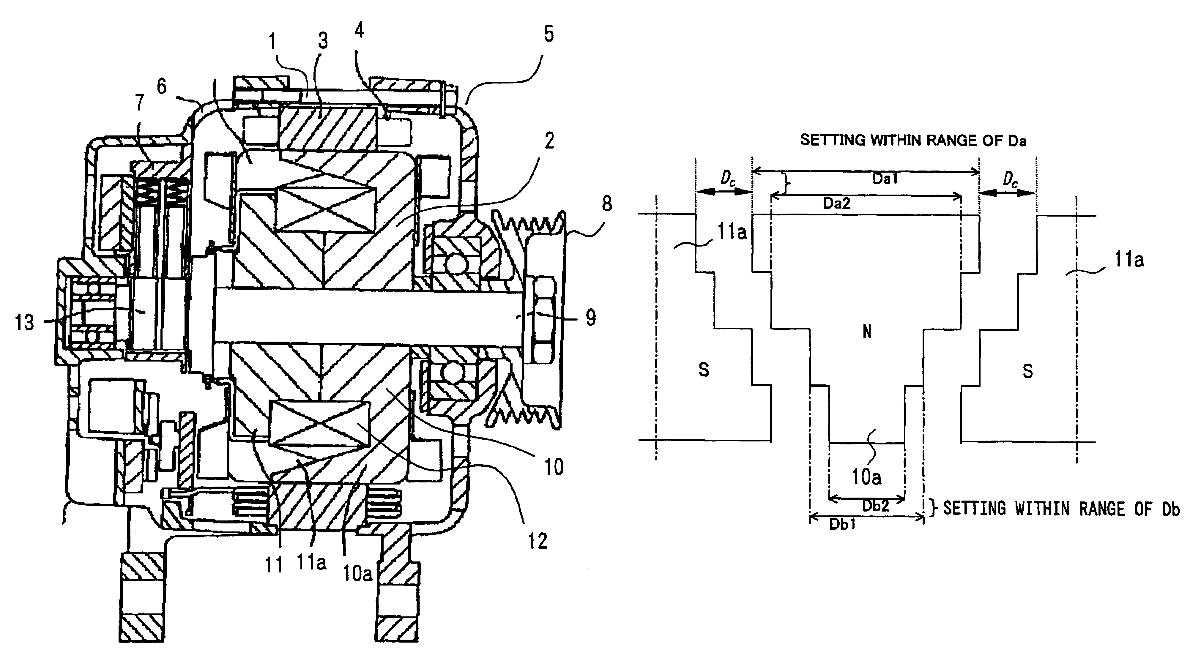
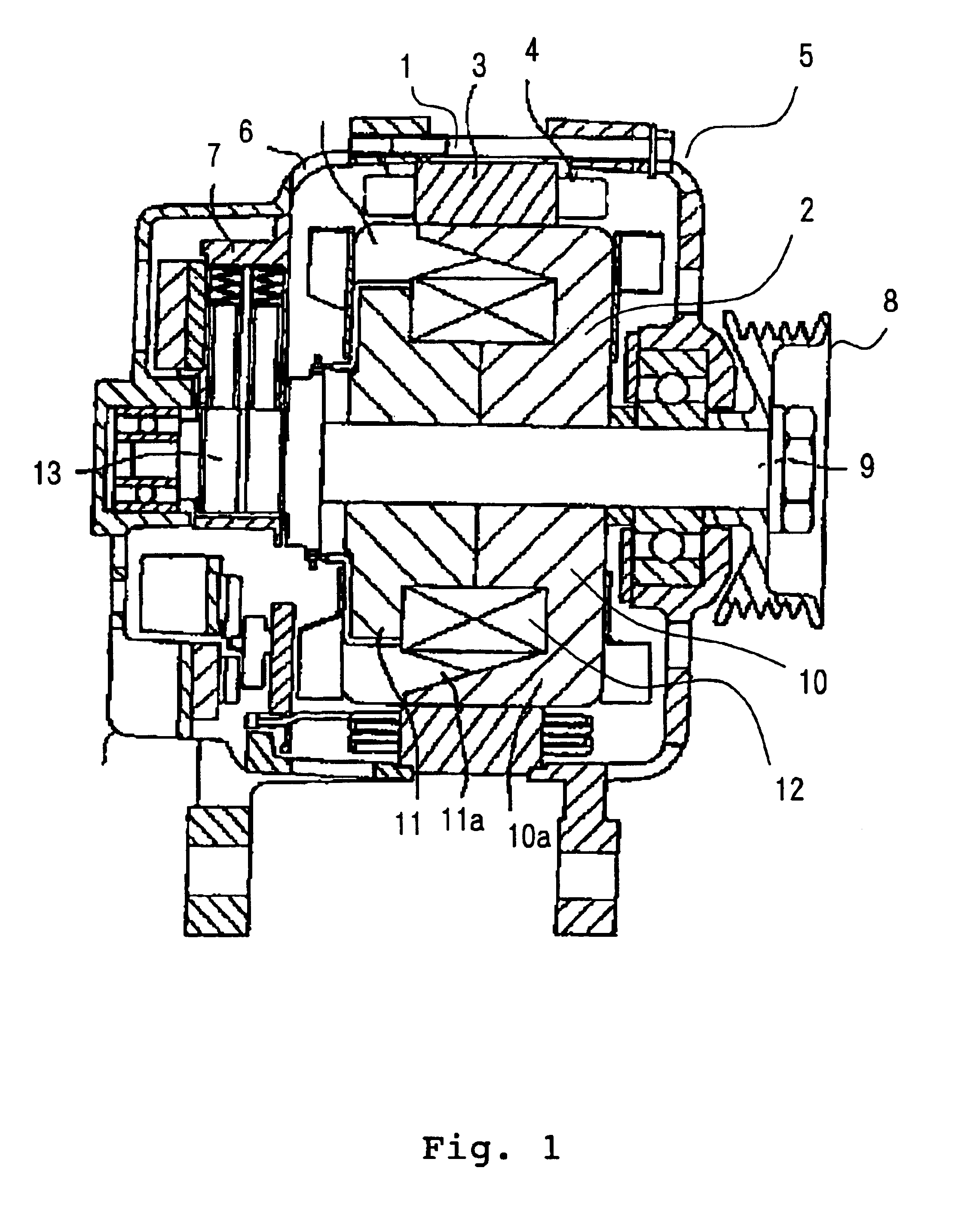
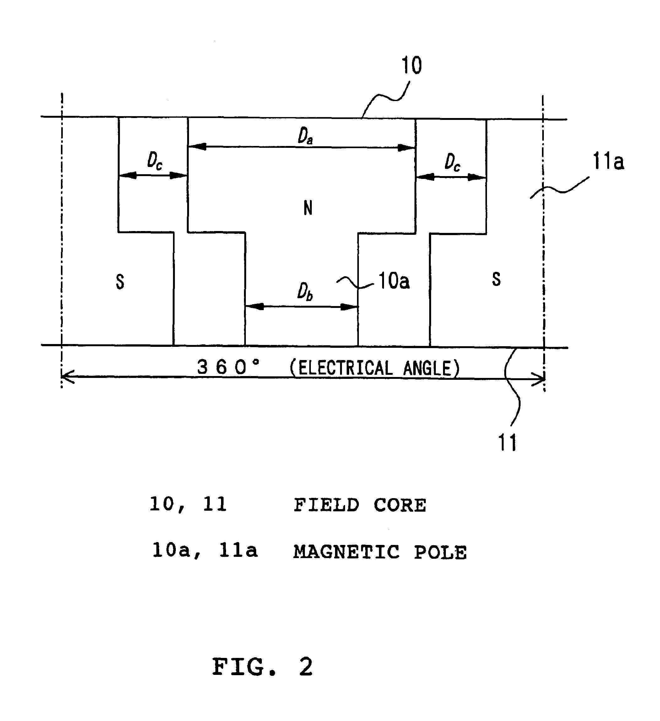
FIGS. 1 to 3 are for explaining a rotating electrical machine for a vehicle according to embodiment 1 of the invention, and FIG. 1 is a whole structural sectional view of the rotating electrical machine for a vehicle. FIG. 2 is a developed view showing the shapes of magnetic poles of rotor cores and shows a case where each of the shapes of the magnetic poles has a two-step structure. FIG. 3 is a characteristic view showing the ratio of the third harmonic to the fundamental wave, that is, the relative third harmonic content, with respect to a clearance between magnetic poles.

In FIG. 1, the rotating electrical machine for a vehicle is constituted by a stator 1 and a rotor 2. The stator 1 is constituted by an armature core 3 having an armature winding 4, a front bracket 5 and a rear bracket 6 for holding the armature core 3 from both sides, a brush structure 7 for supplying a current to the rotor described later, and the like. The armature winding 4 is the winding corresponding to mult...

embodiment 2

FIG. 4 is a characteristic view showing the relative fifth space harmonic content with respect to the magnetic pole width Da (electrical angle) or Db, and in this embodiment, an attempt is made to reduce the fifth space harmonic. The fifth space harmonic of the rotor 2, next to the third space harmonic, influences the electromagnetic exciting force and the torque ripple by the interaction with the slot harmonic of the armature core 3, and is required to be reduced together with the third space harmonic.

In the two-step structure magnetic pole as shown in FIG. 2 in the embodiment 1, the relative fifth space harmonic content is changed by the magnetic pole widths of the magnetic poles 10a and 11a as shown in FIG. 4. With respect to the magnetic pole widths Da and Db in FIG. 2, the magnetic pole width for reducing the fifth space harmonic is expressed by

(206°−Dc)≦Da≦(226°−Dc)  (2)

(134°−Dc)≦Db≦(154°−Dc)  (3),

and in the case where the clearance Dc between the magnetic poles is 60° in elec...

embodiment 3

FIG. 5 is a developed view of a magnetic pole used for a rotating electrical machine for a vehicle according to embodiment 3 of the invention, and in this embodiment, as shown in the drawing, the shape of the magnetic pole is made to have a multi-step structure. In the two-step structure of FIG. 2 described in the embodiment 1, in order to make the clearance Dc between the magnetic poles constant over the whole length of the magnetic pole, the step part of the N pole and the step part of the S pole have the same position in the axial direction, and accordingly, unless the respective values of Da and Db described in the embodiment 2 are set to values close to minimum values in the ranges of the expression (2) and the expression (3), a distance between adjacent magnetic poles at the step parts becomes small, and a leak magnetic flux between the magnetic poles is increased. The increase of the leak magnetic flux results in the lowering of the performance in the case where the function ...


PUM


Abstract

A rotating electrical machine for a vehicle includes a stator having a multi-phase armature winding, a rotor having a pair of field cores which rotate together with a rotating shaft, and a field winding for magnetizing the pair of field cores, the pair of field cores respectively includes magnetic poles extending in an axial direction of the rotating shaft and being arranged to alternately engage with each other through a predetermined clearance Dc, each of the magnetic poles having a width in a rotation direction thereof is formed in a stair shape to be smaller toward a tip of the width, and the clearance Dc between adjacent the magnetic poles is set within a range from 50° to 70° in electrical angle. As a result, the rotating electrical machine for a vehicle can be obtained in which exciting force of harmonic components is reduced, electromagnetic noise, torque ripple and the like are effectively suppressed, and the productivity is excellent.

Description

BACKGROUND OF THE INVENTION1. Field of the InventionThe present invention relates to a rotating electrical machine for a vehicle including a field winding, and particularly to noise reduction of a generator or a generator motor.2. Description of the Related ArtA magnetic field generated by a rotor magnetic pole of an AC generator or an AC generator motor mounted in a vehicle is not a complete sine wave, but has a waveform including higher harmonics. Besides, a magnetic field by a generating current flowing through an armature winding also includes higher harmonics, and by the interaction of both magnetic fluxes including the higher harmonics, magnetic sucking force is generated between a magnetic pole of a field core as a rotor and an armature core as a stator, and harmonic components of the sucking force generate electromagnetic oscillation, and generate noise, so-called electromagnetic noise. Besides, the harmonic components of the magnetic flux generate torque ripple when a gener...

Claims


Application Information

Patent Timeline
Patent Type & Authority Patents(United States)
IPC IPC(8): H02K1/22H02K1/24H02K19/26H02K19/16H02K19/22
CPCH02K1/243H02K19/26
Inventor KOMETANI, HARUYUKIINOUE, MASAYAASAO, YOSHIHITOFUJITA, MASAHIKOYOSHIZAWA, TOSHIYUKIAKITA, HIROYUKI
Owner MITSUBISHI ELECTRIC CORP
Why Eureka
Try Eureka