Hand-held tester and method for local area network cabling

a local area network and tester technology, applied in the field of hand-held testers and methods for local area network cabling, can solve the problems of link failure, limited test life of adapters, and technician work, and achieve the effect of low cost and easy operation

a local area network and tester technology, applied in the field of hand-held testers and methods for local area network cabling, can solve the problems of link failure, limited test life of adapters, and technician work, and achieve the effect of low cost and easy operation

US6847213B2Inactive Publication Date: 2005-01-25IDEAL IND NETWORKS LTD

Image

  • Hand-held tester and method for local area network cabling
  • Hand-held tester and method for local area network cabling
  • Hand-held tester and method for local area network cabling

Examples


Embodiment Construction

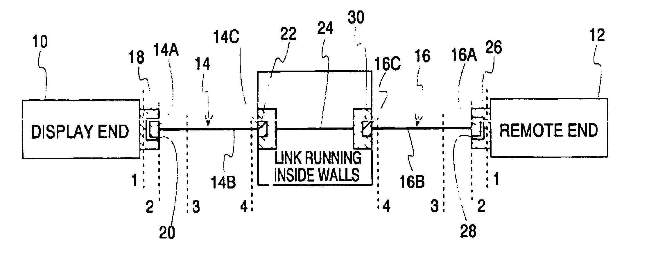
A schematic representation of the LAN testing system of the present invention is shown in FIG. 9. The testing systems includes a hand-held display unit 10, a hand-held remote unit 12 and first and second patch cords 14 and 16. Each patch cord comprises a first plug 14A, 16A at one end, the actual cable 14B, 16B and a second plug 14C, 16C at the other end. The display unit 10 has a channel link adapter board 18 on which is mounted a first connector jack 20. The jack is exposed to the exterior of the display unit. Jack 20 can receive the plug 14A or 16A of a patch cord to form a first mated connector pair. When shooting a link, the other plug 14C, 16C of the patch cord mates with a wall jack 22 attached to the link 24 running inside the walls. The remote unit 14 similarly has a channel link adapter board 26 on which is mounted a second connector jack 28. Both of the connectors 20 and 28 are preferably right-angle connectors with appropriate pair-to-pair isolation. An RJ-45 jack or a S...


PUM


Abstract

A LAN tester has display and remote units each having a connector jack attached to an adapter board for connection to the plug of a patch cord. Both the display and remote units have circuits which are capable of measuring the phase between a drive signal voltage and the corresponding coupled or reflected signal due to the drive signal. Scattering parameters for the mated connector pairs and the patch cord itself are measured during a field calibration. A computer in one or both of the tester units stores the measured scattering parameters and uses the scattering parameters to move the reference plane to any desired location along the patch cord. Channel link or permanent link tests can be conducted using the same equipment.

Description

BACKGROUND OF THE INVENTIONLocal area network (LAN) cabling is used to connect equipment such as personal computers, printers and fax machines that pass information between them using high-speed digital signals. This type of high performance cabling is sometimes referred to as telecommunications cable. Since an office contains many computers, computer file servers, printers, and fax machines, the LAN cabling interconnects all of this equipment into a communications network. LAN cabling has been designed to support telecommunication between all of the individual elements of the network.FIG. 1 shows an example of LAN cabling, in a simplified drawing. FIG. 1 shows how the LAN cabling, most of which runs within the building walls, is used to connect the personal computer 1 at someone's desk to the file server 2 in the telecommunications room. The maximum length of cable 3 inside the wall cannot exceed 90 meters. Wall jack connectors 4 are used to connect the cords 5 from the computer an...

Claims


Application Information

Patent Timeline
25 Jan 2005
Publication
US6847213B2
IPC
H04L12/26; H04L12/24
CPC
H04L12/2697; H04L43/50; H04L41/26
Inventors
RENKEN, GERALD W.; DAVIS, KEITH H.