Power amplifier, power amplifying method and radio communication apparatus

Inactive Publication Date: 2005-01-25
PANASONIC CORP
View PDF7 Cites 52 Cited by
  • Summary
  • Abstract
  • Description
  • Claims
  • Application Information

AI Technical Summary

Benefits of technology

Another object of the present invention is to provide a power amplifier,a power amplifying method capable of lowering the impedance of the circuit part on the output side o

Problems solved by technology

That is, it is difficult that the impedance of the circuit part on the output side of the amplifying element at the frequency of the modulating wave is lower, and consequently, it

Method used


Image

  • Power amplifier, power amplifying method and radio communication apparatus
  • Power amplifier, power amplifying method and radio communication apparatus
  • Power amplifier, power amplifying method and radio communication apparatus

Examples


first embodiment

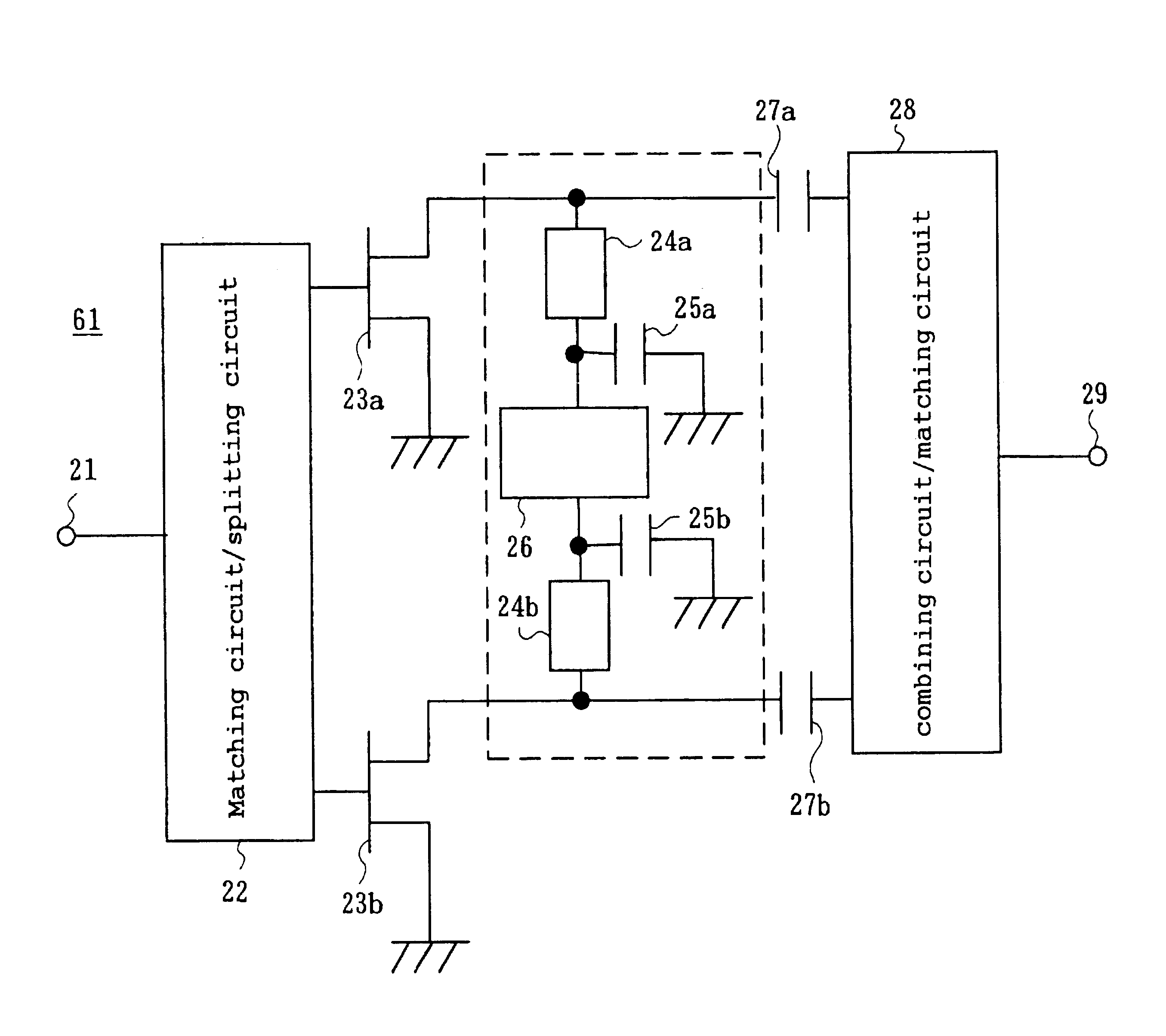
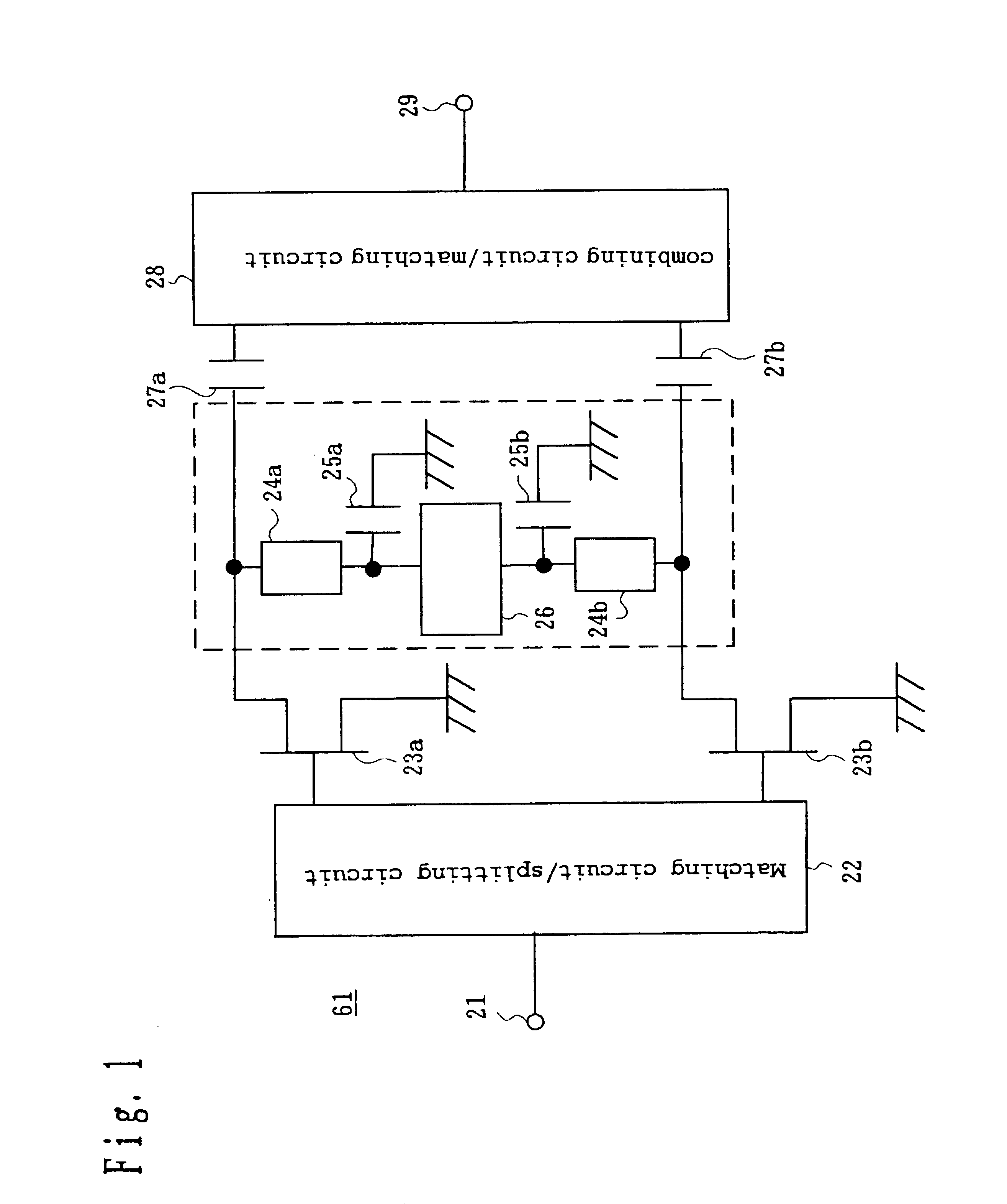
FIG. 1 shows the structure of a power amplifier 61 according to a first embodiment of the present invention.

The power amplifier 61 of FIG. 1 is used, for example, as a power amplifier 5 of a radio circuit 63 shown in FIG. 9.

First, the radio circuit 63 of FIG. 9 will be briefly described.

The radio circuit 63 comprises oscillators 1 and 2, a modulator 3, mixers 4 and 9, the power amplifier 5, a low-noise amplifier 8, a duplexer 6 and an antenna 7.

The modulator 3 is a quadrature modulator that modulates the signal output from the oscillator 1 with a baseband I signal and a baseband Q signal generated by a non-illustrated baseband portion. In the description given below, the frequency of the baseband I signal and the baseband Q signal will be called the frequency of the modulating wave, and it is assumed that the frequency of the modulating wave is, for example, 20 MHz.

The mixer 4 is a circuit that mixes the signal modulated by the modulator 3 with the signal output from the oscillator ...

second embodiment

Next, a second embodiment of the present invention will be described.

FIG. 4 shows the structure of a power amplifier 62 according to the second embodiment.

The power amplifier 62 of the present embodiment is used, for example, as the power amplifier 5 of the radio circuit 63 of FIG. 9 described in the first embodiment.

To an input terminal 21 of the power amplifier 62, the input of a matching circuit / splitting circuit 41 is connected. To the three outputs of the matching circuit / splitting circuit 41, the gate of a FET 42a, the gate of a FET 42b and the gate of a FET 42c are connected, respectively.

The drain of the FET 42a is connected to one of the two inputs of a combining circuit / matching circuit 28 through a capacitor 27a for interrupting direct current. The drain of the FET 42c is connected to the other input of the combining circuit / matching circuit 28 through a capacitor 27b for interrupting direct current. The output of the combining circuit / matching circuit 28 is connected to ...


PUM


Abstract

It is difficult that the impedance of the circuit part on the output side of an amplifying element at the frequency of a modulating wave is lower, and consequently, it is difficult to more effectively use the linearity of the amplifying element. The phase of a signal of the frequency of the modulating wave included in an amplified signal output from a FET is inverted by a difference frequency inverting circuit. The inverted signal of the frequency of the modulating wave and a signal of the frequency of a modulated wave included in an amplified signal output from a FET cancel each other out at the drain of the FET. At the drain end of the FET, the signal of the frequency of the modulating wave included in the amplified signal of the FET and a signal of the frequency of the modulating wave output from the FET cancel each other out.

Description

BACKGROUND OF THE INVENTION1. Field of the InventionThe present invention relates to a power amplifier, a power amplifying method amplifying high-frequency power, and a radio communication apparatus using the power amplifier.2. Description of the Prior ArtIt is required that for size reduction and power saving, power amplifiers used for portable telephone terminals and base stations have high-power and high-efficiency characteristics. In particular, when wide-band transmission signals such as W-CDMA signals are handled, it is necessary that power amplifiers have a wide band and little distortion.However, the frequency spectrum of a modulated wave whose carrier wave is modulated by a modulating wave is normally distributed in a band of approximately the frequency of the modulating wave. When a signal of the frequency of the modulated wave having such a frequency spectrum is input to a power amplifier, because of the nonlinearity of an amplifying element such as a FET (field effect tr...

Claims


Application Information

Patent Timeline
IPC IPC(8): H03F3/60
CPCH03F3/604H03F2200/372H01L2224/48091H01L2224/49175H01L2924/00014
Inventor ISHIDA, KAORUMATSUYOSHI, TOSHIMITSUMIYAJI, MASAYUKI
Owner PANASONIC CORP
Why Eureka
Try Eureka