Supercharge Your Innovation With Domain-Expert AI Agents!

Nonuniform compression span

a compression span and non-uniform technology, applied in the field of non-uniform compression span, can solve the problems of affecting the overall performance of the system, the time required to decompress the desired data, and the delay of access to the uncompressed data, so as to reduce the latency of the communication system

Inactive Publication Date: 2005-01-25
INT BUSINESS MASCH CORP
View PDF6 Cites 10 Cited by
  • Summary
  • Abstract
  • Description
  • Claims
  • Application Information

AI Technical Summary

Benefits of technology

This approach significantly reduces latency in data retrieval by minimizing decompression delays and maintaining efficient compression ratios, even for smaller data portions, thereby enhancing system performance.

Problems solved by technology

In a communication system where data is compressed before transmission and decompressed at the receiver, three kinds of access delays to the uncompressed data are introduced: a delay due to the initialization of the compressor, an initialization delay due to the decompressor, and, if only a portion of the transmitted data is of interest, the time required to decompress the desired data.
A typical example is given by a computer system, where compression is used to improve the utilization of certain resources, such as memory and communication bandwidth, but where the compression / decompression delays can impact the overall performance of the system.
However, when a data request is made, the full latency penalty is paid.

Method used


Image

  • Nonuniform compression span
  • Nonuniform compression span
  • Nonuniform compression span

Examples


Embodiment Construction

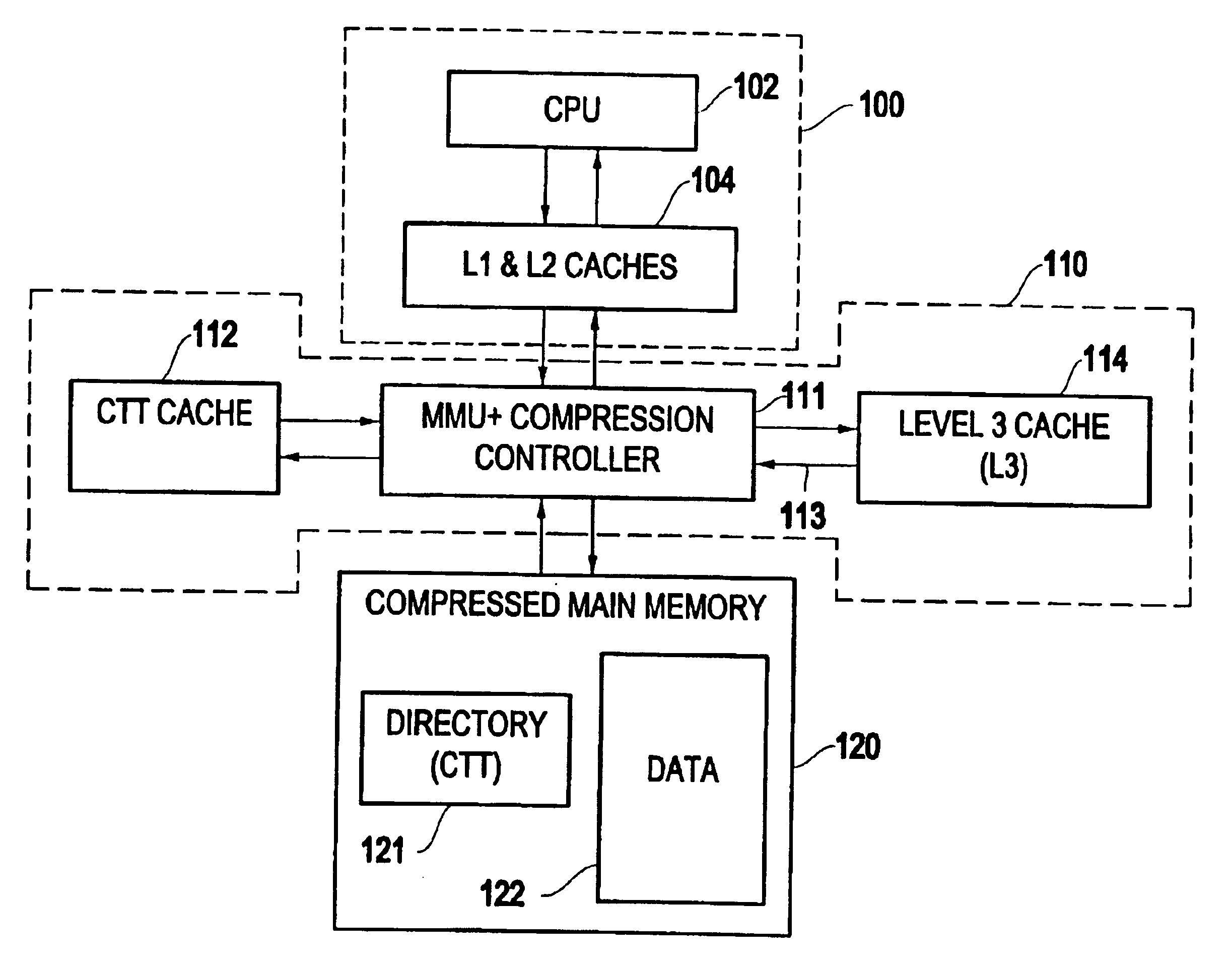
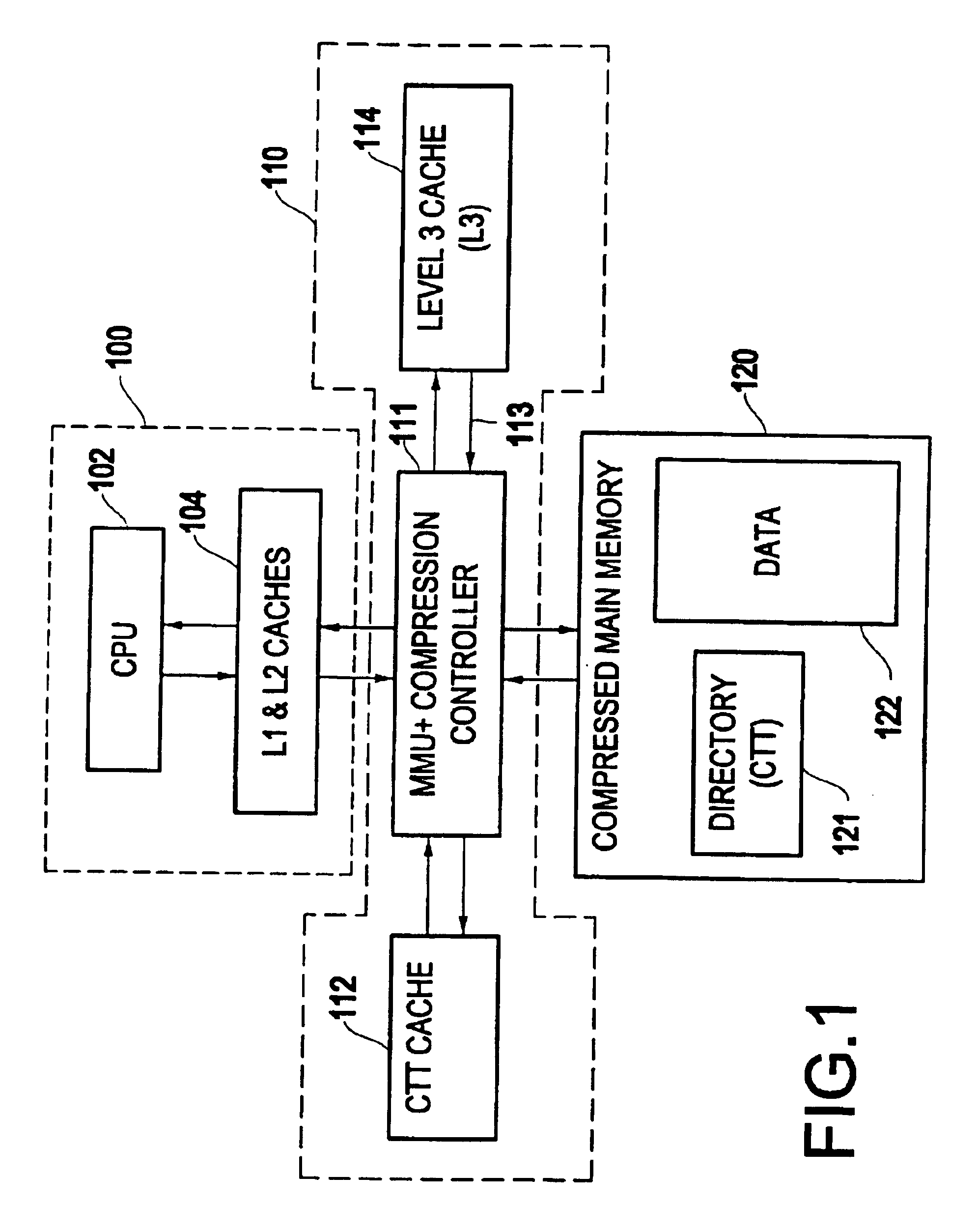
FIG. 1 depicts an exemplary system having features of the present invention. A computer system can be logically divided into a CPU and cache subsystem (100), a memory subsystem (120) and a memory control unit (110), which provides an interface between the CPU and the memory. The CPU and cache subsystem typically contain the CPU (102), one or more L1 caches, and one or more L2 caches (104). The subsystem also has a Translation Lookaside Buffer (TLB) or a hierarchy of TLBs, which are caches used to translate virtual addresses (as generated by processes) into real addresses (as stored in the caches and manipulated by the MMU). In a compressed-memory system, such as the MXT (Memory Extension Technology) architecture (available from International Business Machines Corporation, Armonk N. Y., USA), the compressed main memory 120 is logically divided into a directory (121) and a data portion (120). The directory is used to translate real addresses (as generated by the processor subsystem) i...


PUM


Abstract

A method and structure stores and / or transmits and receives data in compressed form. Retrieval latencies are reduced by selectively transmitting a portion of the data in uncompressed form. When the apparatus is part of a computer architecture supporting main memory compression, a selected L2 cache line belonging to the unit of main memory compression is kept uncompressed. To minimize decompression latency, the uncompressed L2 cache line is stored with the compressed-memory directory. Alternatively, the uncompressed L2 cache line is stored in the compressed memory together with the rest of the memory compression unit it belongs to.

Description

BACKGROUND OF THE INVENTION1. Field of the InventionThe present invention relates to a system where digital communication involves compressing the data at the transmitter and decompressing the data at the receiver. The field covers traditional communication systems, such as wireless communication, cable, fiber optic, as well as internal communication between parts of devices or apparatus, such as the communication between processors and between processors and memories in a computer system.2. Description of the Related ArtIn a communication system where data is compressed before transmission and decompressed at the receiver, three kinds of access delays to the uncompressed data are introduced: a delay due to the initialization of the compressor, an initialization delay due to the decompressor, and, if only a portion of the transmitted data is of interest, the time required to decompress the desired data. In many applications, it is desirable to reduce these delays. A typical example ...

Claims


Application Information

Patent Timeline
Patent Type & Authority Patents(United States)
IPC IPC(8): G06F12/08H03M7/30
CPCG06F12/08H03M7/3088G06F12/0802G06F2212/401
Inventor CASTELLI, VITTORIOFRANASZEK, PETER A.
Owner INT BUSINESS MASCH CORP
Features
  • R&D
  • Intellectual Property
  • Life Sciences
  • Materials
  • Tech Scout
  • Unparalleled Data Quality
  • Higher Quality Content
  • 60% Fewer Hallucinations
Learn More