Self-contained, on-board, CAN-to-fieldbus converter and method of using the same

a converter and can-to-fieldbus technology, applied in the field of self-contained, on-board, can-to-fieldbus converters and methods of using the same, can solve the problem of not communicating with the preexisting vehicle computer network

Inactive Publication Date: 2005-01-25
SHEPPARD MULLIN RICHTER & HAMPTON
View PDF1 Cites 58 Cited by
  • Summary
  • Abstract
  • Description
  • Claims
  • Application Information

AI Technical Summary

Benefits of technology

Accordingly, an aspect of the invention involves a method of communicating a message between an automotive device of an automotive control area network and a non-automotive, industrial device of a non-automotive, fieldbus network. For the purposes of this invention, a fieldbus network is defined to be any data communications network specified by hardware and software protocols with formats native to the industrial device that are different from the protocols that specify the automotive control area network. The method includes receiving a message of a native format from either one of the automotive devices of the automotive control area network or one of the non-automotive, industrial devices of the non-automotive, fieldbus network; translating the original native message format to a common language format; processing the message of a common language format via a set of stored, configurable rules; translating the processed message of a common language format to the appropriate destination native message format; and delivering the message of destination native format to the desired automotive device or non-automotive, industrial device.

Problems solved by technology

A problem with industrial automation components is that they do not communicate with the preexisting vehicle computer networks.

Method used


Image

  • Self-contained, on-board, CAN-to-fieldbus converter and method of using the same
  • Self-contained, on-board, CAN-to-fieldbus converter and method of using the same
  • Self-contained, on-board, CAN-to-fieldbus converter and method of using the same

Examples


Embodiment Construction

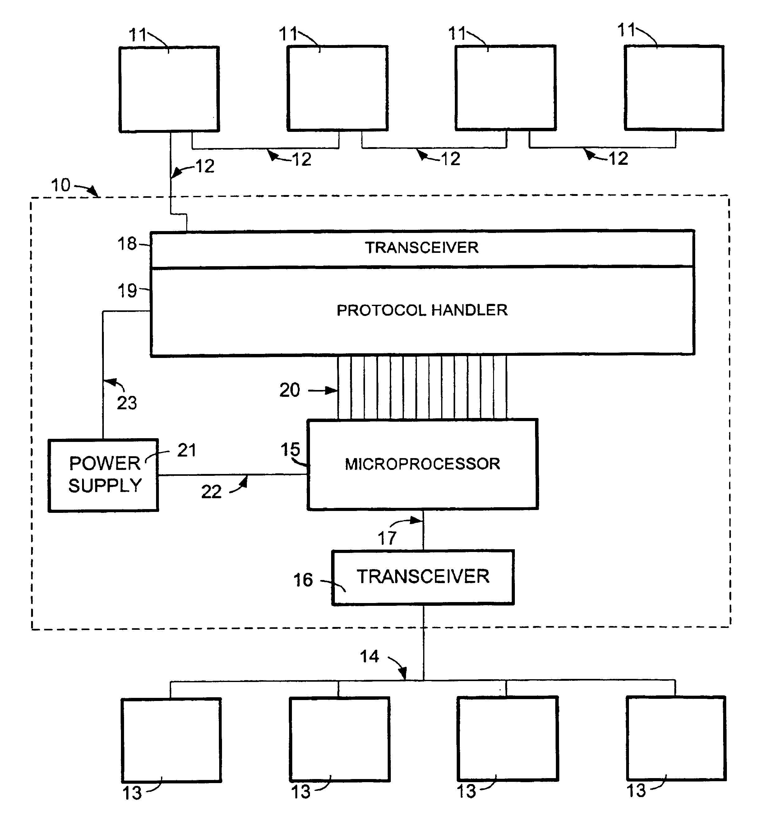
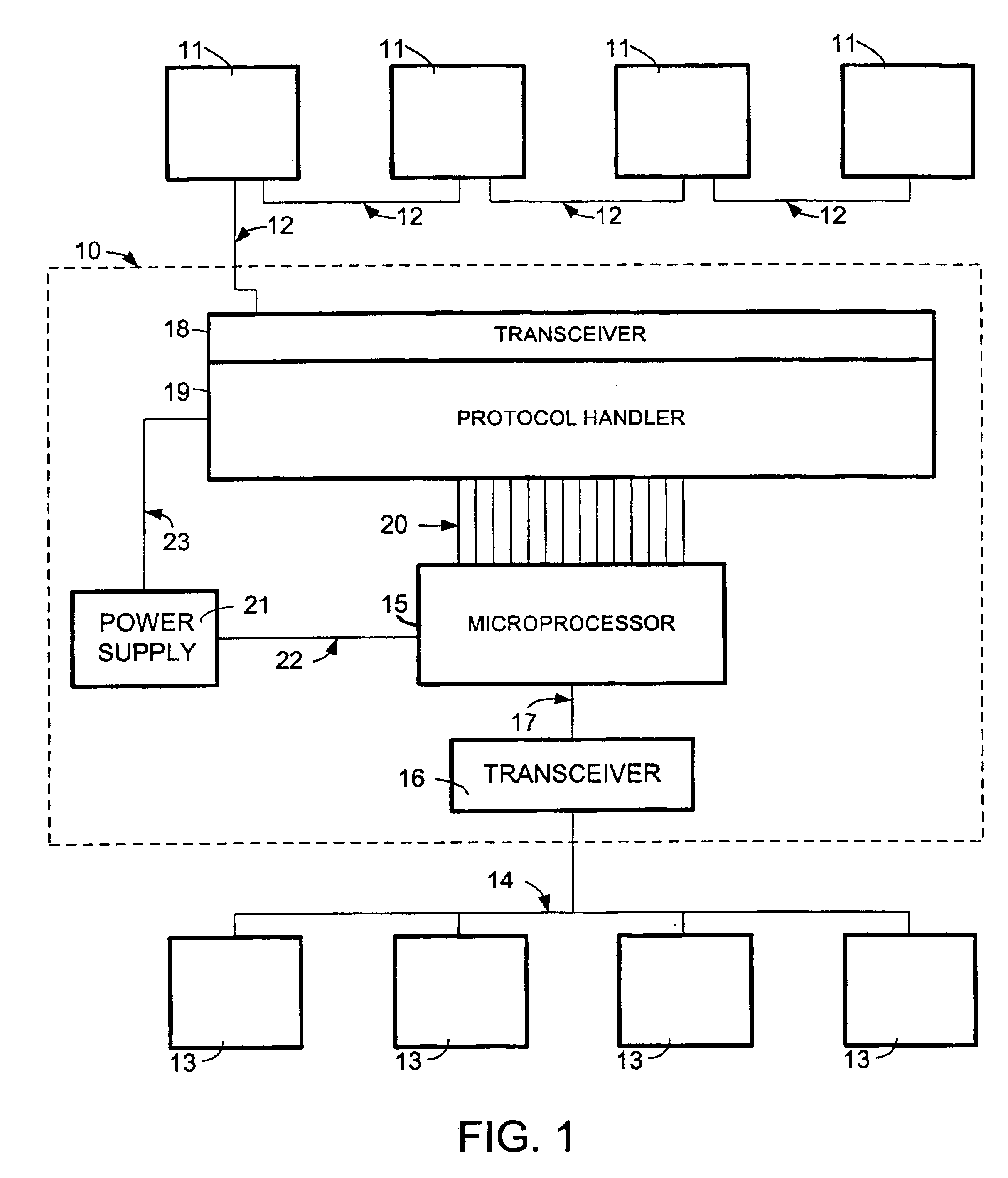
With reference to FIG. 1, an embodiment of a self-contained, on-board, CAN-to-fieldbus converter (“converter”) 10 for communicating non-automotive, industrial automation devices or components (“industrial devices”) 11 on a fieldbus network 12 (any of a number of industrial network protocols available) and automotive computers or devices (“automotive devices”) 13 on a control area network (“CAN”) 14 is shown. The converter 10 includes a CAN-capable microprocessor 15, a vehicle network transceiver 16, and a combination industrial network transceiver 18 and protocol handler 19. The transceiver 16 may be connected to the microprocessor 15 via a serial bus 17 and the protocol handler 19 may be connected to the microprocessor 15 via a parallel bus 20. Each of these components will be described in turn below.

Industrial Devices

In regard to the industrial devices 11, exemplary industrial devices 11 include, but not by way of limitation, an entire electrically powered air conditioning system ...


PUM


Abstract

A method of communicating a message between an automotive device of an automotive control area network and a non-automotive, industrial device of a non-automotive, fieldbus network includes receiving a message of a source format from one of the automotive device of the automotive control area network and the non-automotive, industrial device of the non-automotive, fieldbus network; translating the message of the source format to a common language format; processing the message of a common language format via a set of stored, configurable rules; translating the processed message of a common language format to a destination message format; and delivering the message in the appropriate destination format to one of the automotive device and the non-automotive, industrial device.

Description

FIELD OF THE INVENTIONThe field of the invention relates to systems and methods for use on heavy-duty surface vehicles to interface on-board computers and control area networks (“CANs”) to industrial devices, components, and subsystems not specifically designed for use on vehicles.BACKGROUND OF THE INVENTIONMany modern heavy-duty vehicles include on-board computers interconnected with high-speed data links. The dashboard, engine, and transmission may each have a specialized computer, all sharing the same communications protocol. Because each device, component, and subsystem is specifically built to function as part of an integrated vehicle system, all the control and status-reporting data communications interfaces are originally designed to be compatible with a vehicle CAN standard.Recently, there is a trend toward running high-powered accessories (e.g., air conditioning, steering, and braking) electrically using industrial automation components not specifically designed for vehicle...

Claims


Application Information

Patent Timeline
Patent Type & Authority Patents(United States)
IPC IPC(8): H03M7/00H04L12/417
CPCH04L69/18H04L12/66G05B2219/31135G05B2219/31136G05B2219/31369H04L2012/40215H04L2012/4026H04L2012/40273Y02P90/02
Inventor KELLER, JESSE PETER
Owner SHEPPARD MULLIN RICHTER & HAMPTON
Why Eureka
Try Eureka