Mobile telecommunication device for simultaneously transmitting and receiving sound and image data

a mobile telecommunication device and sound and image technology, applied in the field of telecommunication devices, can solve the problems of wasting valuable treatment time, consuming time and shipping costs, and insufficient communication by phone, so as to eliminate the cost and delay of shipping images and other diagnostic information, and avoid delay. high cost

Inactive Publication Date: 2005-01-25
IMIGE
View PDF22 Cites 53 Cited by
  • Summary
  • Abstract
  • Description
  • Claims
  • Application Information

AI Technical Summary

Benefits of technology

The invention provides an alternative solution that avoids the delay and high cost of shipping images and enables a user to provide a diagnosis from a remote location via simultaneous transmission of voice, image and possibly other data. Specifically, the invention provides a mobile telecommunication unit that sends audio and image information simultaneously and eliminates the cost and delay of shipping images and other diagnostic information. The device is portable, supports a variety of modes of telecommunication (e.g., POTS, cellular, ISDN, T-1, or satellite), and can send voice data and possibly other sounds simultaneously with image data.
The pointers may be instantaneously removed from the image or stored with the image for future reference. In this regard, the above mentioned case notes can refer to pointers added to and saved with the image. This correlation between the text and image information speeds the review and comprehension of the patient information.
Yet another application of the invention is in the insurance industry. An insurance claims agent can survey damage, and immediately send the information to the central office. This allows accurate, on-the-spot claim processing, saves shipping costs, and provides more effective customer service.
In yet another application, an engineer could check the progress of a project across town or across the country without having to waste time traveling to the location. Viewing the project would allow a more accurate analysis than a verbal description over the phone. It would save unnecessary trips, time, and money.
The invention can provide a significant improvement in providing medical services. A doctor in a rural location could consult with a specialist in another region, providing service to a community not presently available. The patient may not have to be transported hundreds of miles for treatment that could have been performed in their hometown, saving thousands of dollars in ambulance fees. An emergency medical technician could consult with the emergency room doctor, and start treatment on the way to the hospital, saving the most valuable time in trauma treatment. A doctor on call could diagnose the patient from home, possibly saving unnecessary trips to the emergency room. Alternatively, the doctor could instruct the operating room personnel on special needs for a special procedure, saving valuable treatment time. A physician could send an image to an insurance company for instant approval, instead of waiting the standard two weeks now allocated.

Problems solved by technology

Communicating by phone is inadequate in many cases, and particularly in the medical industry, where it is critical to have visual information to make a thorough diagnosis.
Such devices exist today, but they are very expensive and typically communicate only between two fixed points.
A real estate agent must ship pictures across the country, consuming time and shipping costs.
A rural doctor must consult by telephone and describe the injury, usually unsatisfactorily, or ship x-rays or other diagnostic data, or even send the patient to the specialist.
All of this takes up valuable treatment time.
In recent years, medical costs have sky-rocketed.
A device that transmits images of patient injuries in a matter of seconds to anywhere in the world would save expensive shipping costs of such images.

Method used


Image

  • Mobile telecommunication device for simultaneously transmitting and receiving sound and image data
  • Mobile telecommunication device for simultaneously transmitting and receiving sound and image data
  • Mobile telecommunication device for simultaneously transmitting and receiving sound and image data

Examples


Embodiment Construction

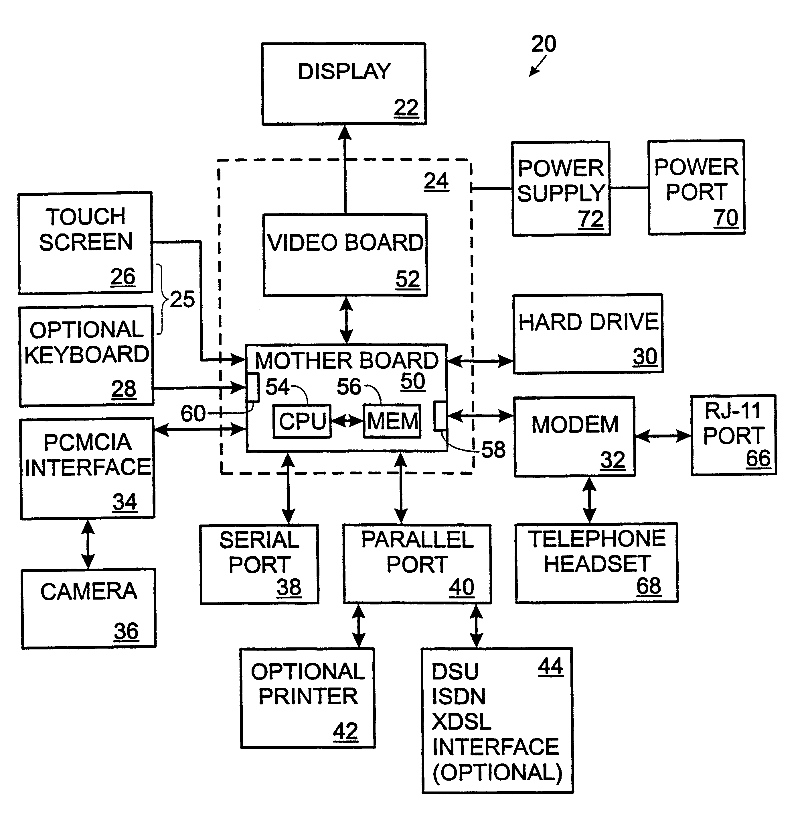
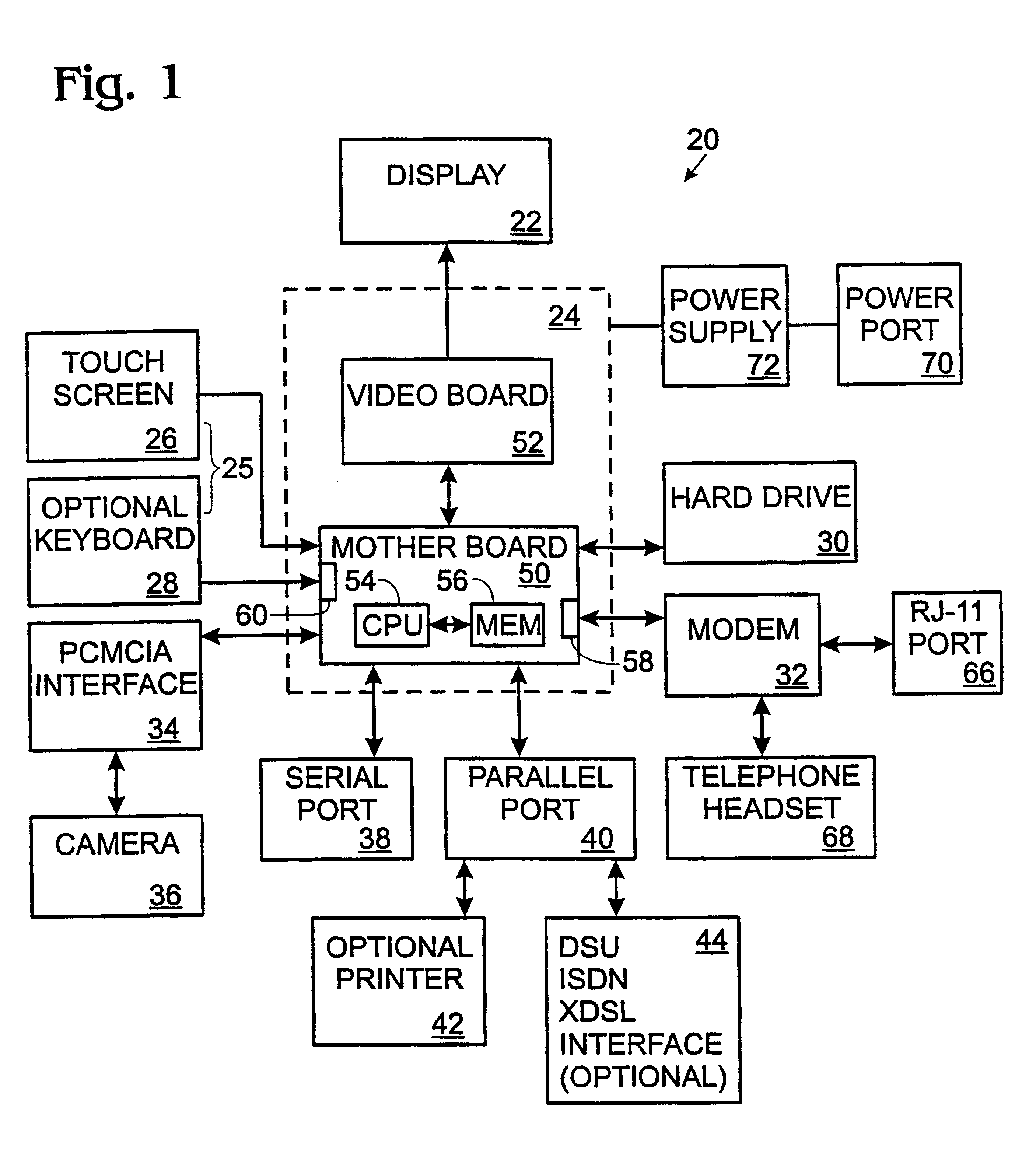
FIG. 1 is a block diagram illustrating an implementation of a mobile telecommunication unit 20 designed according to the invention. The unit 20 includes a display 22, a unit controller 24, a user input device 25 (touch screen 26, and optional keyboard 28), a secondary storage device (hard drive 30), and a modem 32. The unit 20 also includes a number of input / output devices including a camera interface 34 for connecting a camera 36 to the unit controller 24, a serial port 38, and a parallel port 40. The parallel port enables a variety of devices to be connected to the unit including a printer 42, or an interface 44 for ISDN, DSL (Digital Subscriber Line), or digital modem.

The unit controller 24 is comprised of a motherboard 50 and a video board 52 for controlling the display 22. A central processing unit (CPU) 54 and local memory unit 56 are mounted to the motherboard 50, which is implemented using an ISA / PC 104 board from Advanced Computer Solutions, Inc. The CPU 54, an 80 / 486-DX4 b...


PUM


Abstract

A mobile telecommunication unit (20) provides two-way remote viewing of images and real time audio. The self-contained, portable unit (20) communicates directly with a similar unit at a remote location across POTS lines, cellular, ISDN, T-1, and satellite communication links. The unit (20) includes mass storage for archiving images. Input devices (25) for each unit include a digital camera (36) through a PCMCIA card, electronic stethoscope, telephone handset, speakerphone, external microphone, and serial and parallel ports. The output devices include a full color screen (22) for viewing local and received images and a speaker for audio output. A hard copy of images can be made by a video printer or desktop printer (42). Images can be uploaded to a PC.

Description

TECHNICAL FIELDThe invention generally relates to a telecommunication device that allows remote consultation in a variety of fields such as medicine, real estate, insurance, engineering. More particularly, it allows an expert to take part in analysis of an event from a remote location by two-way transmission of sound and image data.BACKGROUNDIn many industries, the ability to converse and share images with an individual located remotely can provide a great advantage. Communicating by phone is inadequate in many cases, and particularly in the medical industry, where it is critical to have visual information to make a thorough diagnosis. A device that could send visual information on the spot would save time, and money in shipping costs. Such devices exist today, but they are very expensive and typically communicate only between two fixed points.Many industries in today's economy could take advantage of a portable and versatile device that could communicate still images and audio to r...

Claims


Application Information

Patent Timeline
Patent Type & Authority Patents(United States)
IPC IPC(8): G06F1/16G06F3/033G06F3/14G06Q10/00H04N7/14H04N1/00G06Q10/10
CPCG06F1/1613G06F1/1628G06F3/033G06F3/1454G06Q10/10H04N1/00315H04N7/142H04N7/148H04N1/00209H04N2201/0086H04N1/00307H04N2201/0084
Inventor HAYHURST, BILLWARD, FREDERICK H.DABNEY, JAMES H.
Owner IMIGE
Why Eureka
Try Eureka