
Gas laser apparatus emitting ultraviolet radiation

a laser and ultraviolet radiation technology, applied in the direction of laser details, electrical devices, active medium materials, etc., can solve the problems of large output light peak power, degraded projection exposure system performance, and it is difficult with the conventional technique to realize a longer pulse width, and achieve the effect of expanding the oscillation pulse width

Inactive Publication Date: 2005-01-25
USHIO DENKI KK
View PDF15 Cites 4 Cited by
  • Summary
  • Abstract
  • Description
  • Claims
  • Application Information

AI Technical Summary

Benefits of technology

In view of the above-described problems with the prior art, an object of the present invention is to extend the oscillation pulse width in gas laser appa...

Problems solved by technology

Therefore, the peak power of the output light is large.
For this reason, the optical elements of the projection exposure system may be damaged by a compaction (an increase in refractive index), etc., causing the performance of the projection exposure system to be degraded.
It is actually difficult with the conventional technique to realize a longer pulse width in the demanded high-repetition rate oscillating operation.

Method used


Image

  • Gas laser apparatus emitting ultraviolet radiation
  • Gas laser apparatus emitting ultraviolet radiation
  • Gas laser apparatus emitting ultraviolet radiation

Examples


Embodiment Construction

The principle of the present invention, together with an embodiment thereof, will be described below with reference to the accompanying drawings.

The present inventors have succeeded in realizing a high-repetition rate and extended-pulse width oscillating operation of an ArF excimer laser apparatus by adopting an approach entirely different from those in the prior art. First, the principle of the present invention will be described below.

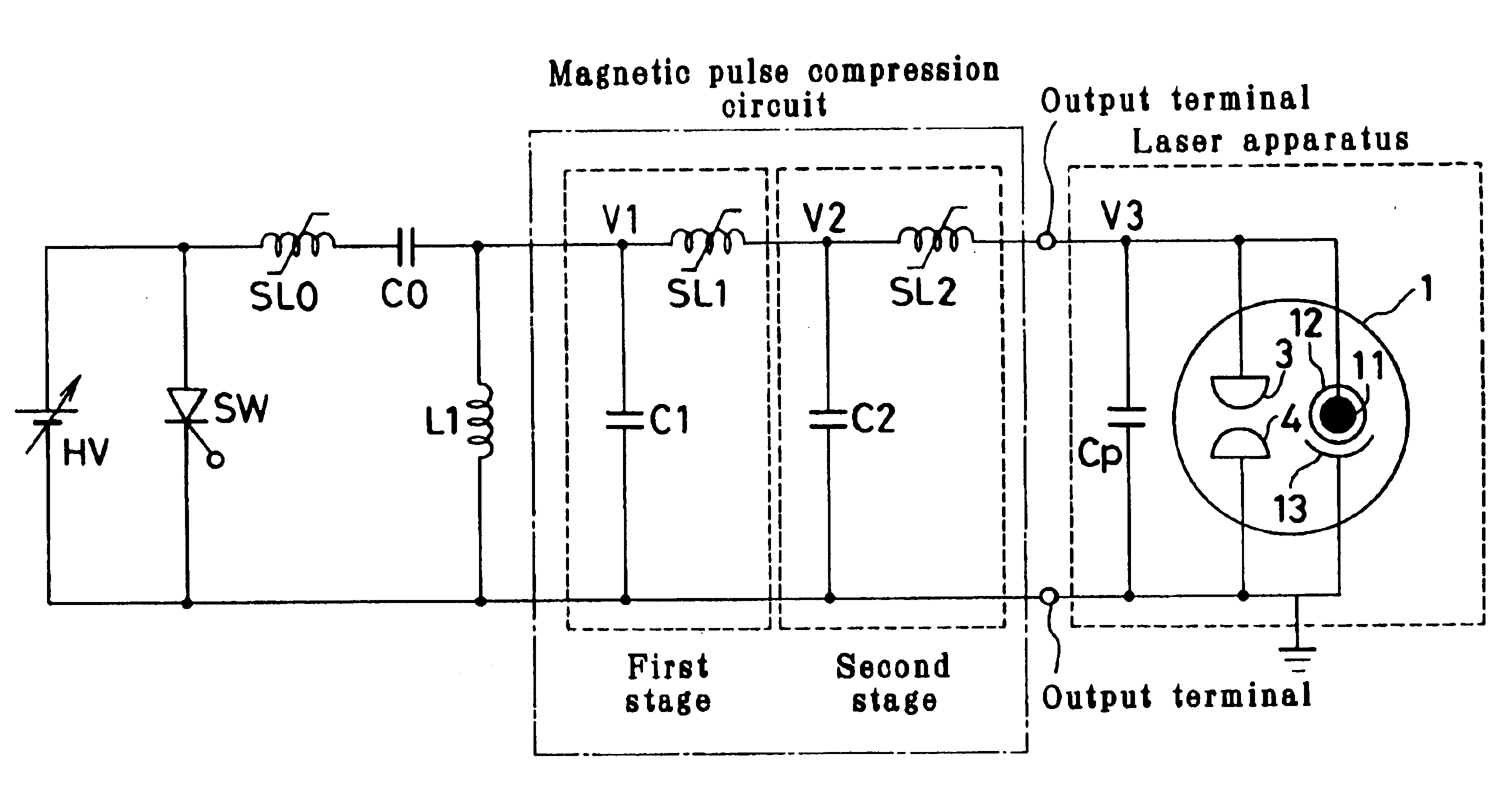
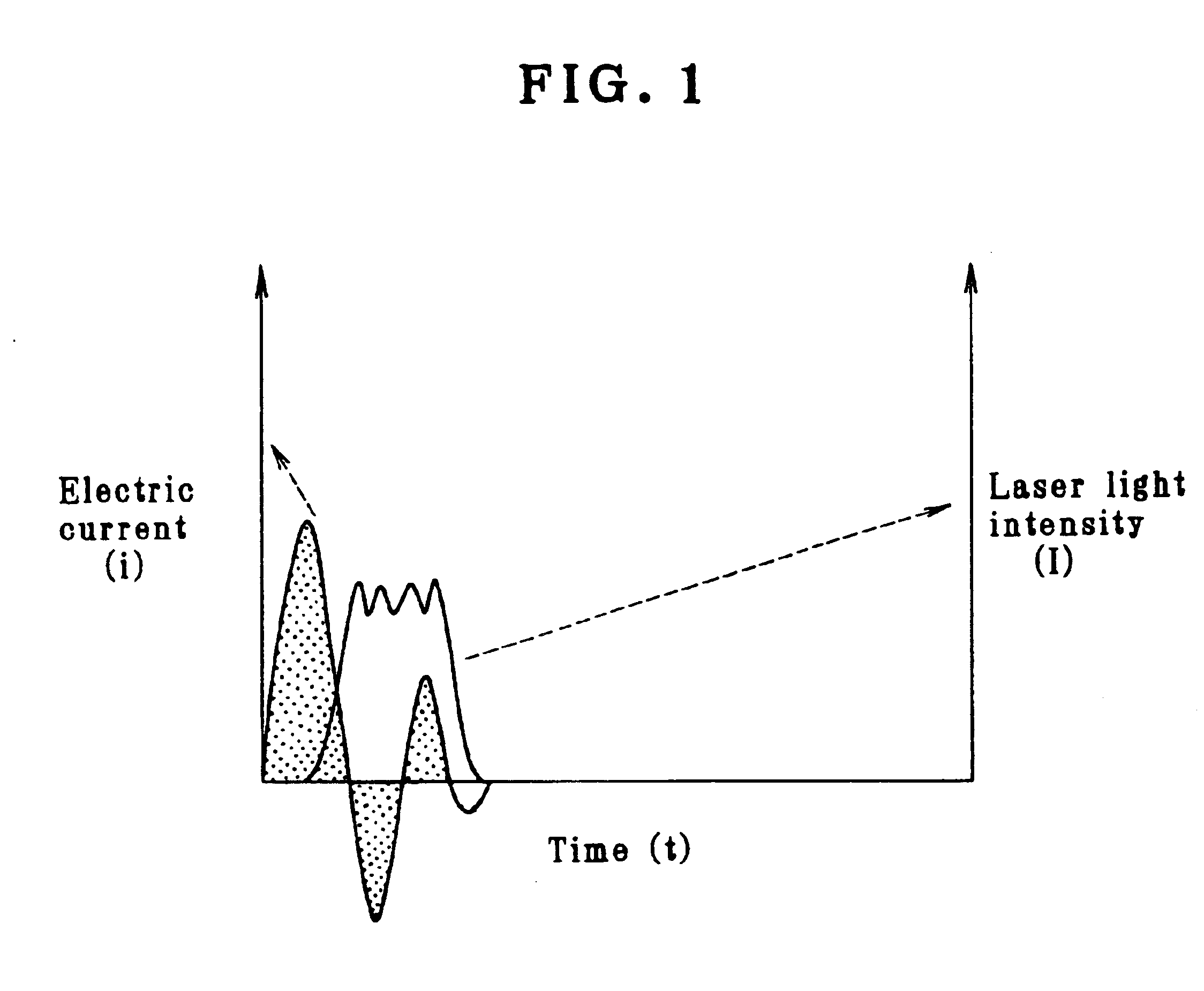
As a result of exhaustive studies, the present inventors have found that it is possible to realize a longer pulse width by determining circuit constants so that the period of the oscillating current flowing between the discharge electrodes is shortened and, at the same time, the peak value of the current is increased.

More specifically, it has heretofore been considered that only the first half-cycle of the oscillating current contributes to the laser oscillation, as stated above. Actually, the conventional excimer laser apparatus do not perform a las...


PUM


Abstract

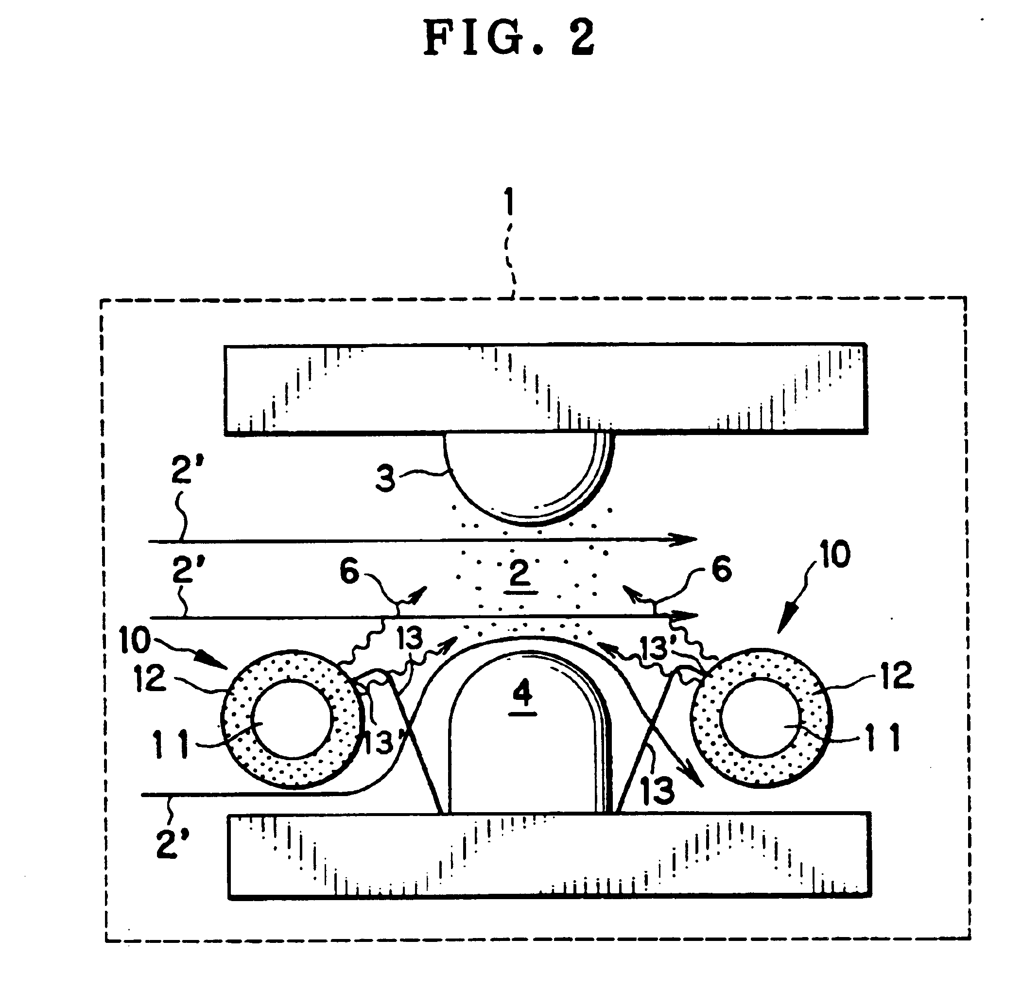
The oscillation pulse width is extended in a gas laser apparatus emitting ultraviolet radiation by a high-repetition rate oscillating operation. The gas laser apparatus has a pair of laser discharge electrodes connected to the output terminals of a magnetic pulse compression circuit and disposed in a laser chamber. The pulse width is extended by determining circuit constants so that the period of the oscillating current flowing between the discharge electrodes is shortened and, at the same time, the peak value of the current is increased, whereby the laser gas is continuously excited even during at least one half-cycle subsequent to the first half-cycle of the oscillating current to sustain the laser oscillating operation.

Description

BACKGROUND OF THE INVENTIONThe present invention relates to gas laser apparatus emitting ultraviolet radiation. More particularly, the present invention relates to gas laser apparatus, i.e. KrF excimer laser, ArF excimer laser, and fluorine laser, which perform a lasing operation with an extended oscillation pulse width.With the achievement of small, fine and high-integration semiconductor integrated circuits, it has been demanded that projection exposure systems for the manufacture of such highly integrated circuits be improved in resolution. Under these circumstances, the wavelength of exposure light emitted from light sources for lithography is becoming shorter, and gas laser apparatus emitting ultraviolet radiation are promising as next-generation light sources for semiconductor lithography, i.e. KrF excimer laser of wavelength 248 nm, ArF excimer laser of wavelength 193 nm, and fluorine laser of wavelength 157 nm.In these excimer laser apparatus, a laser gas is sealed in a lase...

Claims


Application Information

Patent Timeline
IPC IPC(8): H01S3/0971H01S3/14H01S3/225H01S3/038H01S3/097H01S3/02
CPCH01S3/0971H01S3/0384H01S3/225H01S3/09716H01S3/02
Inventor KAKIZAKI, KOJISAITO, TAKASHIWATANABE, HIDENORI
Owner USHIO DENKI KK
Learn More