
Gas laser apparatus

A gas laser, gas technology, used in lasers, laser parts, electrical components, etc.

Inactive Publication Date: 2006-12-06
FANUC LTD
View PDF1 Cites 4 Cited by
  • Summary
  • Abstract
  • Description
  • Claims
  • Application Information

AI Technical Summary

Problems solved by technology

However, it has never been done to directly adjust the composition of the medium gas used to optimize the characteristics (or quality) of the laser beam as the properties of the workpiece or the machining accuracy change.

Method used


Image

  • Gas laser apparatus
  • Gas laser apparatus
  • Gas laser apparatus

Examples


Embodiment Construction

[0021] Embodiments of the present invention will be described in detail below with reference to the drawings. In the drawings, the same or similar constituent units are assigned common reference signs.

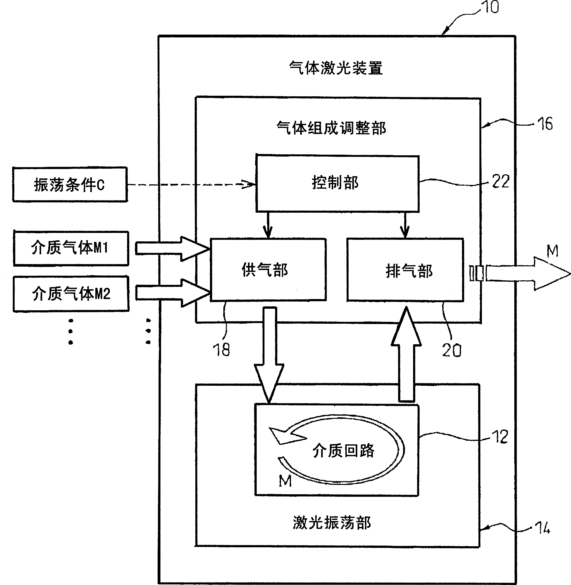
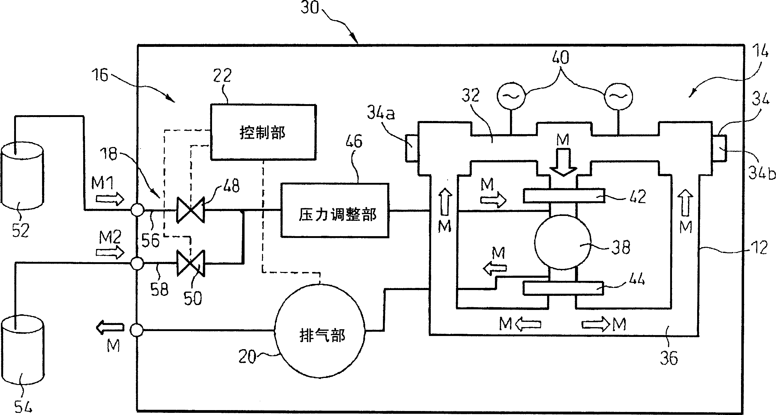
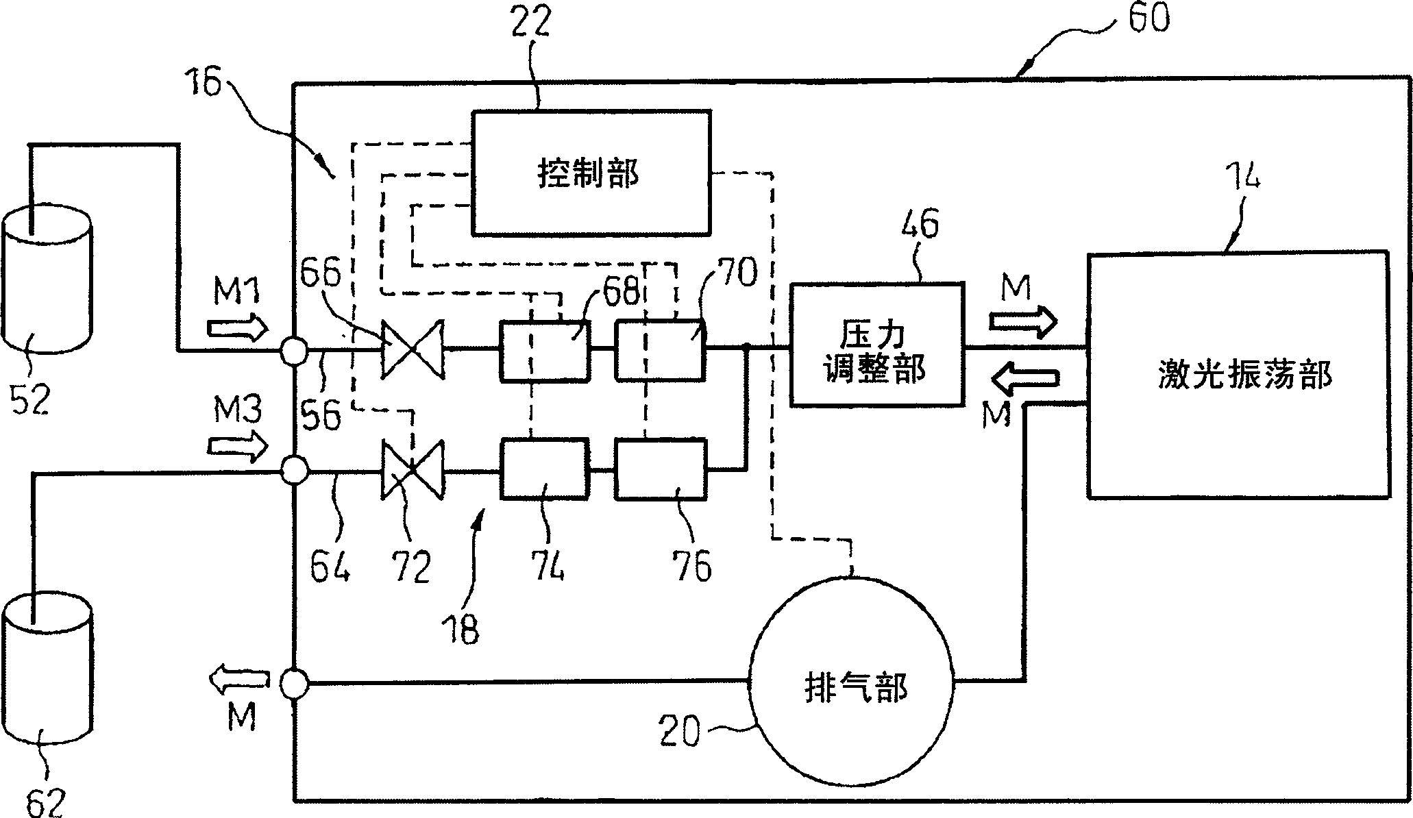
[0022] With reference to the accompanying drawings, figure 1 The basic structure of the gas laser device 10 of the present invention is shown in a functional block diagram. The gas laser device 10 includes a laser oscillator 14 having a medium circuit 12 in which a medium gas M flows under pressure, and a gas composition adjustment unit 16 that adjusts the composition of the medium gas M flowing through the medium circuit 12 of the laser oscillator 14 . The gas composition adjustment part 16 is equipped with a gas supply part 18 for supplying a plurality of medium gases M (M1, M2...) with different compositions to the medium circuit 12 of the laser oscillation part 14 in an adjustable flow rate, and from the laser oscillation part 14. The medium circuit 12 discharges the exh...


PUM


Abstract

A gas laser apparatus including a laser oscillating section including a medium circuit allowing a medium gas to flow therethrough under pressure, and a gas-composition adjusting section for adjusting the composition of the medium gas flowing through the medium circuit of the laser oscillating section. The gas-composition adjusting section comprising a gas supply section for supplying several types of medium gases having different compositions to the medium circuit of the laser oscillating section with a flow rate of each of the medium gases being adjustable; a gas exhaust section for exhausting the medium gas from the medium circuit of the laser oscillating section; and a control section for controlling the gas supply section and the gas exhaust section, to adjust the composition of the medium gas flowing through the medium circuit, in accordance with an oscillation condition including at least one of an attribute of an object matter acted on by a laser beam oscillated by the laser oscillating section and the accuracy of action of the laser beam.

Description

technical field [0001] The present invention relates to a gas laser device using gas as a laser medium. Background technique [0002] Gas laser devices using gas as a laser medium are widely used in the fields of processing, medical treatment, and measurement. A laser oscillator constituting a gas laser device generally has an excitation part (by discharge, light, heat, chemical reaction, etc.) The light energy of the medium gas is emitted as a laser beam from the optical resonance part (with a pair of mirrors), the excitation part and the optical resonance part are connected to form a circulation path of the medium circuit in which the medium gas flows under pressure, and the circulation path is set on the circulation path. , It is composed of a blower that forces the medium gas to circulate at a high speed in the medium circuit. [0003] In such a gas laser device, the characteristics (or quality) of the oscillating laser beam are affected by the curvature or reflectance...

Claims


Application Information

Patent Timeline
Patent Type & Authority Applications(China)
IPC IPC(8): H01S3/104H01S3/036H01S3/22
CPCH01S3/036H01S3/2232H01S3/104
Inventor 佐藤孝德村上孝文江川明
Owner FANUC LTD
Learn More