Machine capability verification and diagnostics (CAP/DIA) system, method and computer program product

a technology of capability verification and diagnostics, applied in the direction of mechanical measuring arrangements, instruments, using mechanical means, etc., can solve the problems of increasing the cost of progression (i.e., the cost of tightening the tolerances) beyond a point, and improving the accuracy and repeatability of such machine tools. , the effect of improving the repeatability

Inactive Publication Date: 2005-01-25
THE BOEING CO
View PDF10 Cites 21 Cited by
  • Summary
  • Abstract
  • Description
  • Claims
  • Application Information

AI Technical Summary

Benefits of technology

In one preferred form, the present invention provides a method for verifying the accuracy of a CNC machine or a CMM. The methodology segregates the measured error into an assignable cause portion and a common cause (or random error) portion. The methodology may be employed to affect the calibration of the machine tool to factor out the mean value of the assignable cause portion. Inherent in this methodology is the ability to diagnose mechanical problems with the CNC machine or CMM that effect the repeatability and accuracy of such machine tools; identify degradation in the performance of such machine tools that is indicative of mechanical failure; and improve the accuracy and repeatability of such machine tools in certain situations.

Problems solved by technology

As is well known in the art, the quality of the output from a CNC machine or CMM is a highly complex function that is based in part on the accuracy and repeatability with which the movable elements of the machine tool are movably positioned.
Issues of wear aside, one drawback with this proposition concerns its economics; generally speaking, tolerances may only be tightened to a degree without unreasonable cost penalty, but thereafter substantial costs are incurred so that progression (i.e., the tightening of the tolerances) beyond a point is cost prohibitive.
With that in mind, the various critical machine tool elements of most if not all CNC machines and CMM's used in manufacturing are not capable of positioning a machine tool's movable elements in an extremely accurate manner (i.e., on the order of one ten-thousandth of an inch) without some sort of electronic compensation.
I have found, however, that values for accuracy and repeatability calculated in this manner are too conservative to be of any meaningful value.
As the data in the plot clearly illustrates, however, this conclusion is too conservative.
As this process is repeated for each of the registers in the second set, and as there are often times 50 or more (often times hundreds) registers in the second set for a single axis, the process is rather time consuming and costly (both in terms of the cost of the mechanic's time as well as in machine down-time where it cannot be used in a productive manner).

Method used


Image

  • Machine capability verification and diagnostics (CAP/DIA) system, method and computer program product
  • Machine capability verification and diagnostics (CAP/DIA) system, method and computer program product
  • Machine capability verification and diagnostics (CAP/DIA) system, method and computer program product

Examples


Embodiment Construction

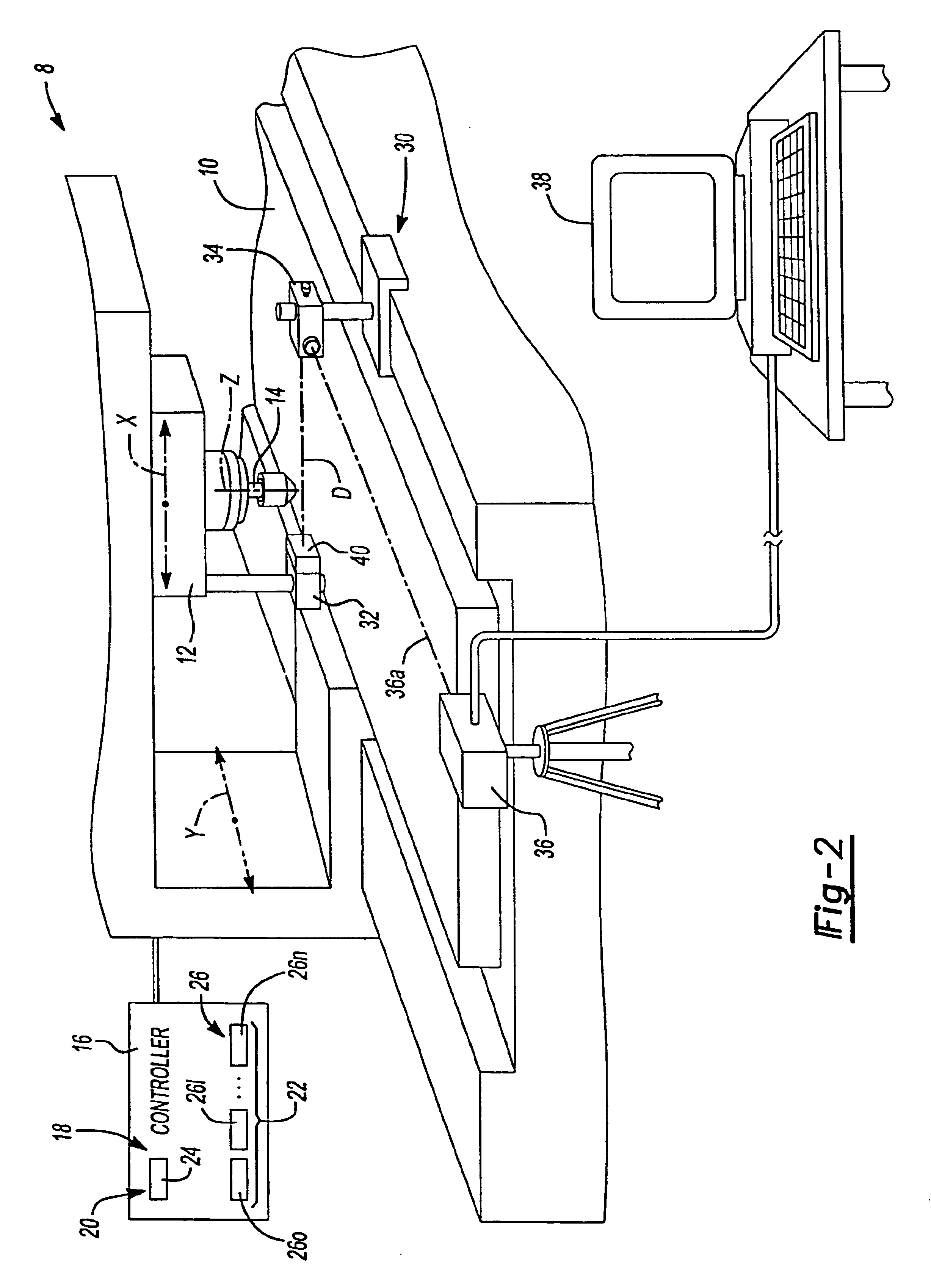
With reference to FIG. 2 of the drawings, an exemplary CNC machine is generally indicated by reference numeral 8. The CNC machine 8 is illustrated to be a conventional vertical machining center of the type that is well known in the art. The CNC machine 8 includes a base 10, a first movable element or tool head 12, which is movable in two orthogonal directions relative to the base 10 as identified by axes X and Y, and a second movable element or spindle 14, which is moveable relative to the base 10 along an axis Z, and a controller 16. Although the CNC machine illustrated and described herein is a vertical machining center, it will be understood that the teachings of the present invention have applicability to all types of CNC machine tools, including but not limited to CMM's, horizontal mills, vertical mills, gantry mills, post mills, spar mills, wire electro-discharge machining (EDM) machines, vertical EDM's, water and plasma jets, routers, saws, etc. Furthermore, the particular CN...


PUM


Abstract

A method for verifying the accuracy of a CNC machine or a CMM. The methodology segregates the measured error into an assignable cause portion and a common cause (or random error) portion. The methodology may be employed to affect the calibration of the machine tool to factor out the mean value of the assignable cause portion. Inherent in this methodology is the ability to diagnose mechanical problems with the CNC machine or CMM that affects the repeatability and accuracy of such machine tools; identify degradation in the performance of such machine tools that is indicative of mechanical failure; and improve the accuracy and repeatability of such machine tools in certain situations.

Description

FIELD OF THE INVENTIONThe present invention generally relates to systems, methods and computer program products for use in conjunction with computer numerically controlled (CNC) machines and coordinate measuring machines (CMM). More particularly, the present invention relates to a method for verifying the accuracy of a CNC machine or a CMM. Inherent in this methodology is the ability to 1) diagnose mechanical problems with the CNC machine or CMM that effect the repeatability and accuracy of such machine tools; 2) identify degradation in the performance of such machine tools that is indicative of mechanical failure; and 3) improve the accuracy and repeatability of such machine tools in certain situations.BACKGROUND OF THE INVENTIONCNC and CMM machine tools are well known in the art and employed in virtually every field of manufacturing for tasks that include, for example, material cutting, material removal and inspection. Typically, these machine tools have one or more movable elemen...

Claims


Application Information

Patent Timeline
Patent Type & Authority Patents(United States)
IPC IPC(8): G01B21/02G01B21/04
CPCG01B21/042
Inventor CHAWLA, MOHINDER PAUL
Owner THE BOEING CO
Why Eureka
Try Eureka