Power reduction circuit and method with multi clock branch control

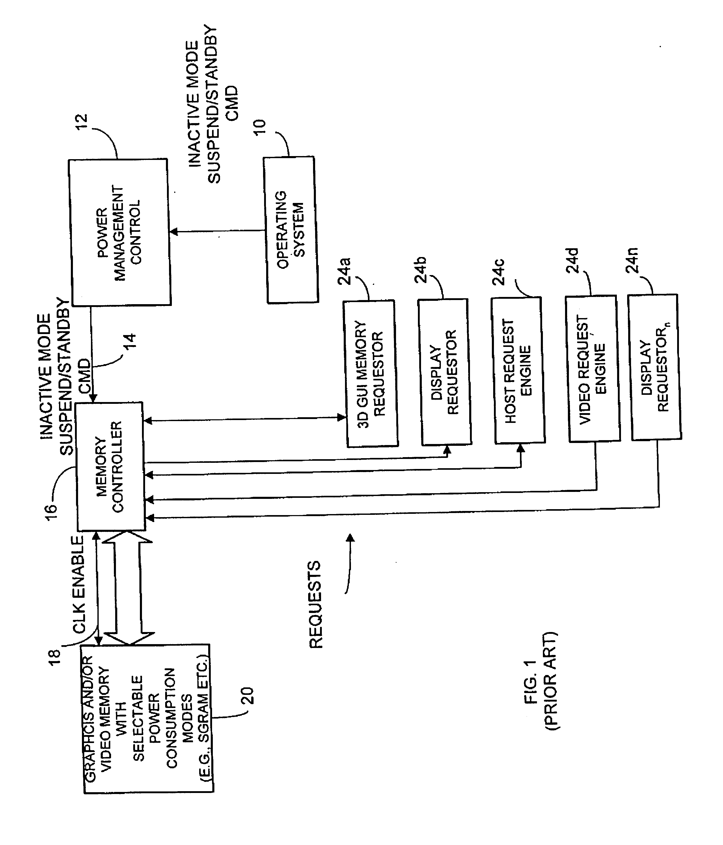
a power reduction circuit and power branch technology, applied in the direction of liquid/fluent solid measurement, sustainable buildings, instruments, etc., can solve the problems of power consumption and thermal dissipation, sacrificing operational performance, and consuming power during display mode of portable electronic devices such as notebook computers

Inactive Publication Date: 2005-01-25
ATI TECH INC
View PDF6 Cites 45 Cited by
  • Summary
  • Abstract
  • Description
  • Claims
  • Application Information

AI Technical Summary

Problems solved by technology

Portable electronic devices such as notebook computers, personal organizers, portable telecommunication equipment and other electronic devices consume much power during their display mode.
However only one of the graphic engines can typically access the memory at a given time.
A problem arises with such devices since power consumption and thermal dissipation needs to be minimized for portable devices without unnecessarily sacrificing operational performance.
Also, the same problem arises for non-portable devices due to increased circuit density and increased clock speeds.
However, such systems do not typically provide suitable power reduction during the active operational mode of the system since the memory clock is always running regardless of which circuits may be idle during the active mode.
During non-read cycles, undesired data is fed through the read path of the chip consuming power and potentially adding additional switching noise.
This typically prevents access to registers for the graphics processing circuits.
This is typically done because the 3D engine, when operational, can consume large amounts of processing capability of the graphics processing circuitry.
However, it is typically done for only the larger processing engines.

Method used


Image

  • Power reduction circuit and method with multi clock branch control
  • Power reduction circuit and method with multi clock branch control
  • Power reduction circuit and method with multi clock branch control

Examples


Embodiment Construction

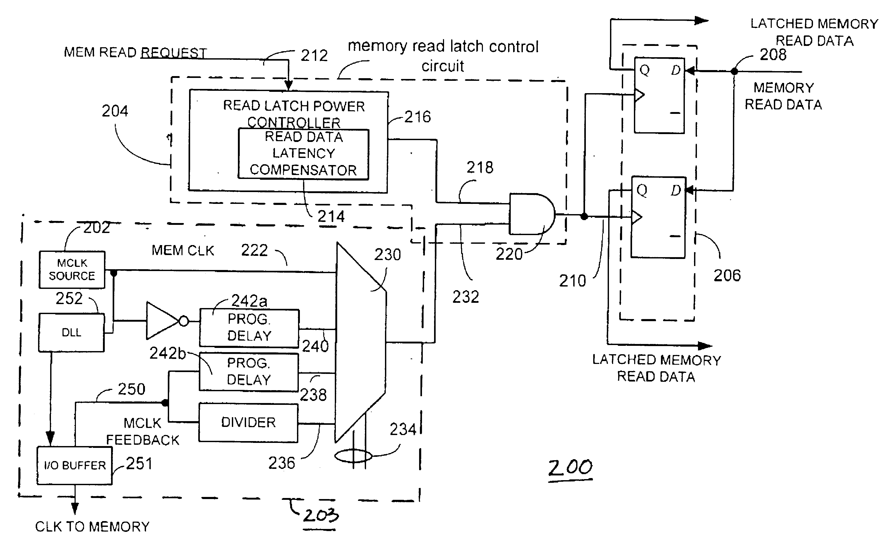
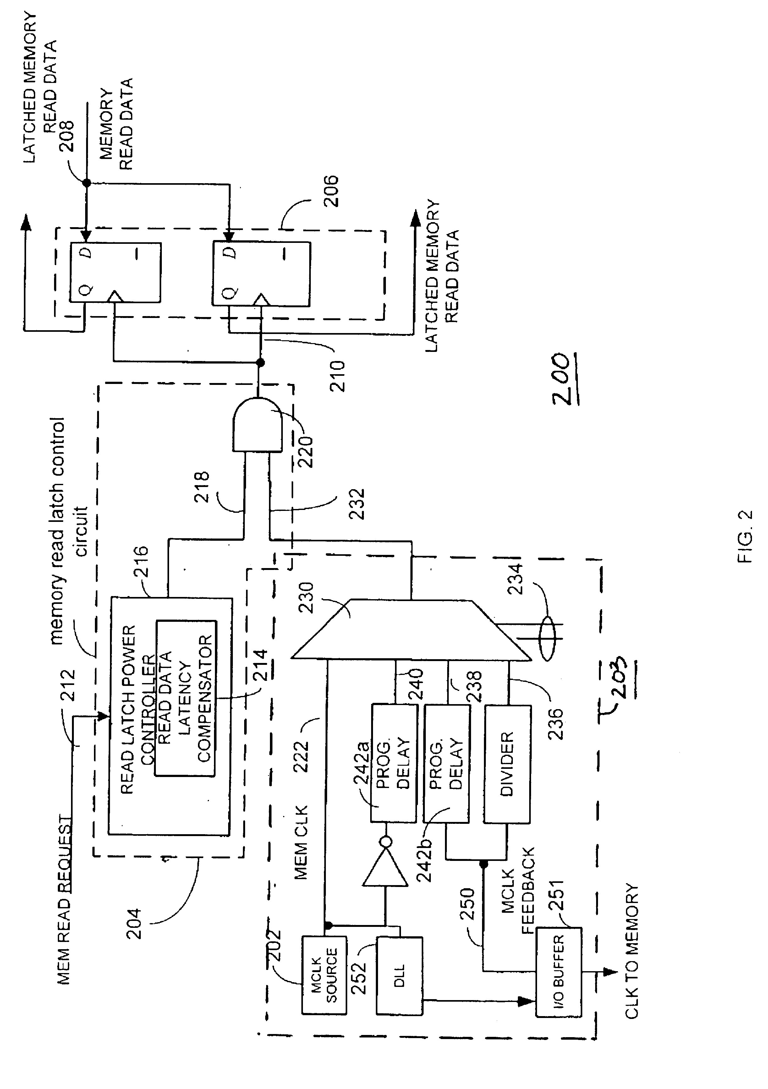
Briefly, a power consumption reduction circuit and method utilizes a memory clock source and a memory clock divider circuit that generates divided memory clock output signals as a plurality of corresponding independent clock signals to a number of memory interface circuits for different processing engines. The memory clock provides clock signals to circuits such as a memory controller and memory interface circuit for memory request engines. The memory interface circuits are used for servicing and managing memory requests. A memory clock divider circuit and method selectively activates a plurality of independent clock signals in response to received condition data. Condition data may be activity based or user defined. Examples of condition data may include, for example, whether a primary or secondary display has been selected, whether a graphic user interface engine is active, whether a video overlay scaler has been enabled, whether subpicture operation has been enabled, and whether ...


PUM


Abstract

A power consumption reduction circuit and method utilizes a memory clock source and a memory clock divider circuit that generates divided memory clock output signals as a plurality of corresponding independent clock signals to a number of different processing engines. A memory clock divider circuit and method selectively activates a plurality of independent clock signals in response to received condition data. In one embodiment, an engine clock source is also coupled through a switching circuit such that it is selectively output to one or more processing engines. The switching circuit disables the output from the engine clock based on register condition data. In another embodiment, a plurality of memory read latch circuits are controlled by a memory read latch control circuit. The memory read latch control circuit is operative to dynamically activate and deactivate the plurality of memory read latches based on detected memory read requests to facilitate memory access activity-based power reduction.

Description

FIELD OF THE INVENTIONThe invention relates generally to circuits and methods for reducing power consumption for electronic circuits, and more particularly to circuits and methods that reduce power consumption for devices employing a memory control.BACKGROUND OF THE INVENTIONPortable electronic devices such as notebook computers, personal organizers, portable telecommunication equipment and other electronic devices consume much power during their display mode. By way of example, graphics control chips for laptop computers may be integrated circuits having synchronous dynamic ram (SDRAM) on the same die as the memory controller, other video and graphics processors, and central processing units if desired. For example, a conventional type of graphics control circuit may include a number of memory access request circuits (or access request engines) such as a video capture engine, a two dimensional and three dimensional drawing engine, a display engine, a video playback engine, a host p...

Claims


Application Information

Patent Timeline
Patent Type & Authority Patents(United States)
IPC IPC(8): G06F1/26G06F1/32
CPCG06F1/3203G06F1/3237G06F1/3275G06F1/3287Y02B60/1228Y02B60/1221Y02B60/1225Y02B60/1282Y02D10/00
Inventor SINCLAIR, DAVID E.YOUNG, ERICHAOUILI, SAMI J.
Owner ATI TECH INC
Why Eureka
Try Eureka