Stock lifter for metal forming dies and method for making the same

a technology of metal forming dies and stock lifters, which is applied in the direction of forging presses, forging/pressing/hammering apparatuses, shaping tools, etc., can solve the problems of large lead time, high cost of metal forming die design, manufacture, repair or modification, etc., and achieve the effect of reducing design, manufacturing and repair costs and easy removal from the di

Inactive Publication Date: 2005-02-01
PYPER TOOL & ENG
View PDF31 Cites 53 Cited by
  • Summary
  • Abstract
  • Description
  • Claims
  • Application Information

AI Technical Summary

Benefits of technology

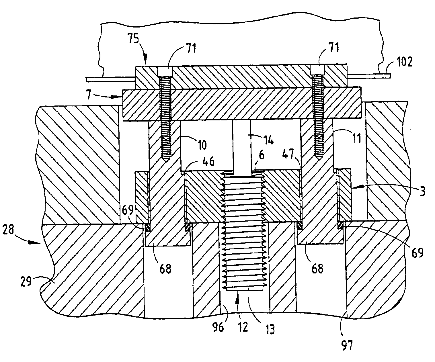
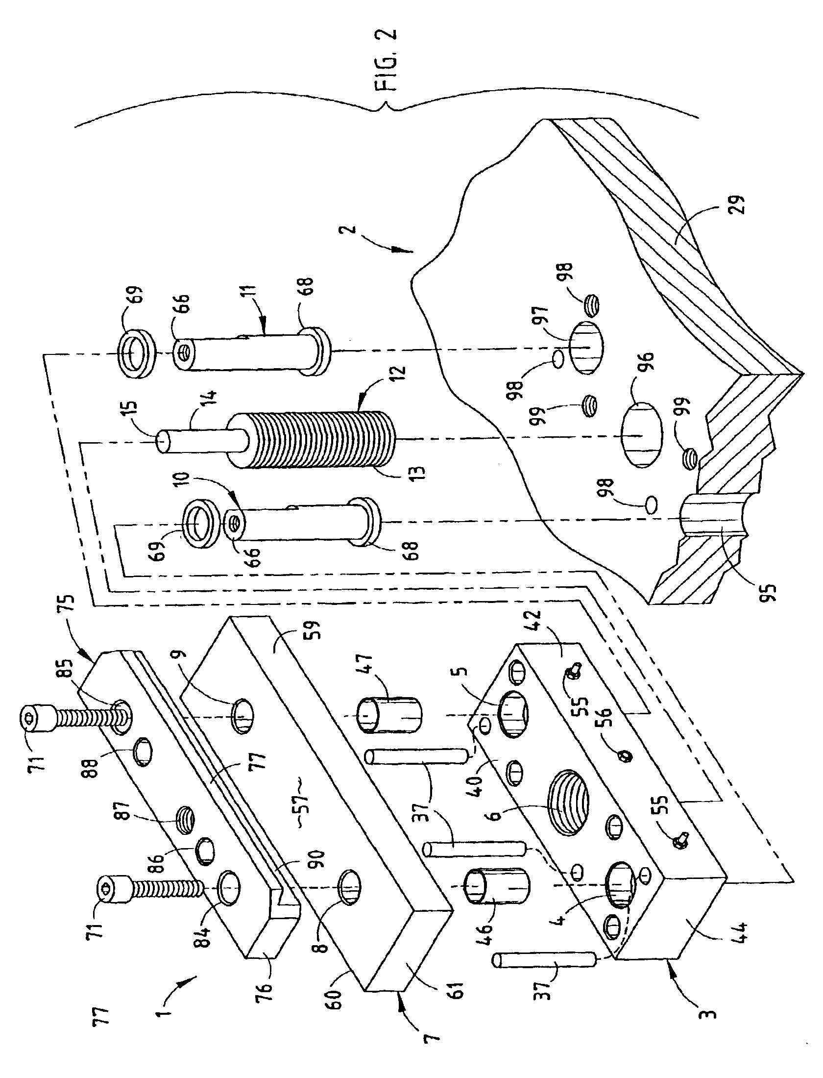
One aspect of the present invention is a progressive metal forming die having a self-contained stock lifter that includes a base plate with two vertical through holes adjacent opposite sides, and a vertical spring unit aperture located between the through holes. The stock lifter also includes a lifter bar having two vertical through holes in vertical registry with the base plate through holes. Two rigid guide shafts are mounted in the base plate through holes to permit the lifter bar to reciprocate in a manner which selectively lifts stock in the die to permit longitudinally shifting the stock along the multiple die stations. A spring unit has a base retained in the spring unit aperture, and a reciprocating rod biased outwardly, with a free end abutting a central portion of the lifter bar to shift the base plate and lifter bar to an extended position, thereby defining a fully self-contained unit that can be readily mounted in and removed from the die to reduce design, manufacturing and repair costs.

Problems solved by technology

Current die making processes require carefully machined, precision holes and recesses in the die set for mounting the individual components, such that the same are quite labor intensive, and require substantial lead time to make, test and set up in a stamping press.
Consequently, such metal forming dies are very expensive to design, manufacture and repair or modify.

Method used


Image

  • Stock lifter for metal forming dies and method for making the same
  • Stock lifter for metal forming dies and method for making the same
  • Stock lifter for metal forming dies and method for making the same

Examples


Embodiment Construction

For purposes of description herein, the terms “upper”, “lower”, “right”, “left”, “rear”, “front”, “vertical”, “horizontal” and derivatives thereof shall relate to the invention as oriented in FIGS. 11 and 12. However, it is to be understood that the invention may assume various alternative orientations and step sequences, except where expressly specified to the contrary. It is also to be understood that the specific devices and processes illustrated in the attached drawings, and described in the following specification, are simply exemplary embodiments of the inventive concepts defined in the appended claims. Hence, specific dimensions and other physical characteristics relating to the embodiments disclosed herein are not to be considered as limiting, unless the claims by their language expressly state otherwise.

The reference numeral 1 (FIG. 2) generally designates a self-contained stock lifter embodying the present invention, which is particularly adapted for use in conjunction wit...


PUM

PropertyMeasurementUnit
lengthaaaaaaaaaa
widthaaaaaaaaaa
thicknessaaaaaaaaaa

Abstract

A self-contained stock lifter is particularly adapted for use in multiple station, progressive metal forming dies and the like, and includes a base plate with two vertical through holes adjacent opposite sides, and a vertical spring unit aperture located between the through holes. The stock lifter also includes a lifter bar having two vertical through holes in vertical registry with the base plate through holes. Two rigid guide shafts are mounted in the base plate through holes to permit the lifter bar to reciprocate in a manner which selectively lifts stock in the die to permit longitudinal shifting of the stock along the multiple die stations. A spring unit has a base retained in the spring unit aperture, and a reciprocating rod biased outwardly, with a free end abutting a central portion of the lifter bar to shift the lifter bar to an extended position, thereby defining a fully self-contained unit that can be readily mounted in and removed from the die to reduce manufacturing and repair costs.

Description

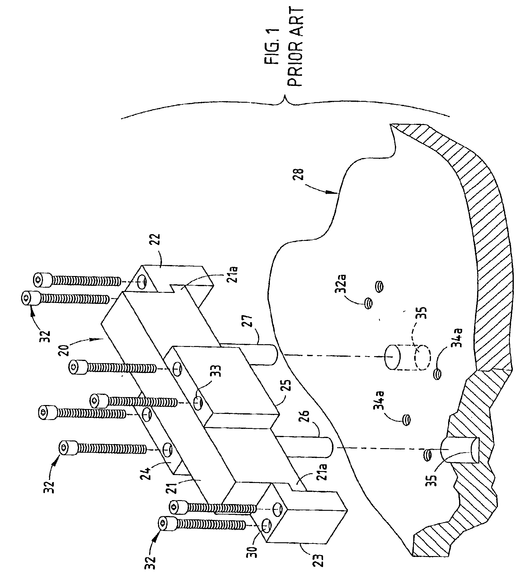
BACKGROUND OF THE INVENTIONThe present invention relates to metal forming dies and the like, and in particular to a stock lifter and method for making the same.Metal forming dies, such as stamping dies and the like, are well known in the art. Progressive metal forming dies are unique, very sophisticated mechanisms which have multiple stations or progressions that are aligned longitudinally, and are designed to perform a specified operation at each station in a predetermined sequence to create a finished metal part. Progressive stamping dies are capable of forming complex metal parts at very high speeds, so as to minimize manufacturing costs.Heretofore, the dies used in metal forming presses have typically been individually designed, one-of a-kind assemblies for a particular part, with each of the various die components being handcrafted and custom mounted or fitted in an associated die set, as shown in FIG. 1, which is in turn positioned in a stamping press. Not only are the punches...

Claims


Application Information

Patent Timeline
Patent Type & Authority Patents(United States)
IPC IPC(8): B21D37/08B21D37/00B21D45/00B21D35/00
CPCB21D35/00B21D45/00B21D37/08Y10T29/49826
Inventor PYPER, JOEL T.PYPER, JOHN K.BREEN, SCOTT M.BROWN, CHARLES T.PYPER, JEFFERY S.
Owner PYPER TOOL & ENG
Why Eureka
Try Eureka