
Capacitive dynamic quantity sensor, method for manufacturing capacitive dynamic quantity sensor, and detector including capacitive dynamic quantity sensor

a capacitive dynamic and sensor technology, applied in the direction of acceleration measurement using interia forces, variable capacitors, instruments, etc., can solve the problem of difficulty in sufficiently and achieve the effect of improving the sensor sensitivity

Inactive Publication Date: 2005-02-01
DENSO CORP
View PDF4 Cites 27 Cited by
  • Summary
  • Abstract
  • Description
  • Claims
  • Application Information

AI Technical Summary

Benefits of technology

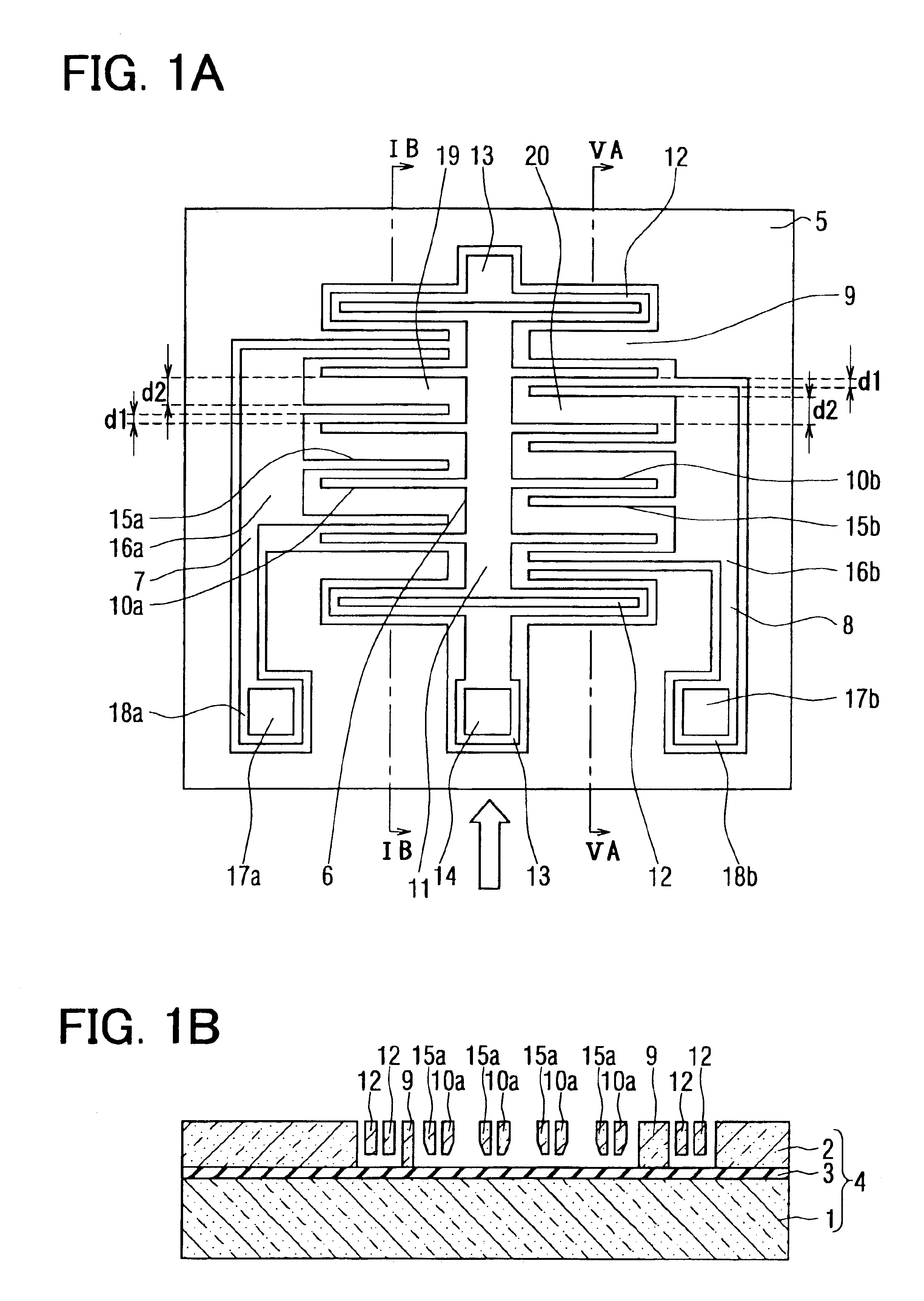
A capacitive dynamic quantity sensor according to the present invention includes a semiconductor substrate, a weight, a movable electrode, and two fixed electrodes. The weight is movably supported by the semiconductor substrate. The movable electrode is integrated with the weight. The fixed electrodes are stationarily supported by the semiconductor substrate. The fixed electrodes face the movable electrode to provide a narrow gap and a wide gap and form a detection part having a capacitance. The weight and the movable electrode are displaced relative to the fixed electrodes in response to a dynamic quantity to be detected such that one of the gaps increases while the other decreases. The dynamic quantity is detected on the basis of the variation in the capacitance. One of wide gap electrode surfaces, which define the wide gap, is smaller than narrow gap electrode surfaces, which define the narrow gap, to improve sensor sensitivity.

Problems solved by technology

However, it is difficult to sufficiently improve the sensor sensitivity by adjusting the distances between the electrodes because the dimension d2 of the wide gaps is limited by the dimensions of the sensor.

Method used


Image

  • Capacitive dynamic quantity sensor, method for manufacturing capacitive dynamic quantity sensor, and detector including capacitive dynamic quantity sensor
  • Capacitive dynamic quantity sensor, method for manufacturing capacitive dynamic quantity sensor, and detector including capacitive dynamic quantity sensor
  • Capacitive dynamic quantity sensor, method for manufacturing capacitive dynamic quantity sensor, and detector including capacitive dynamic quantity sensor

Examples


first embodiment

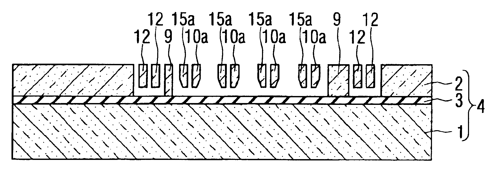
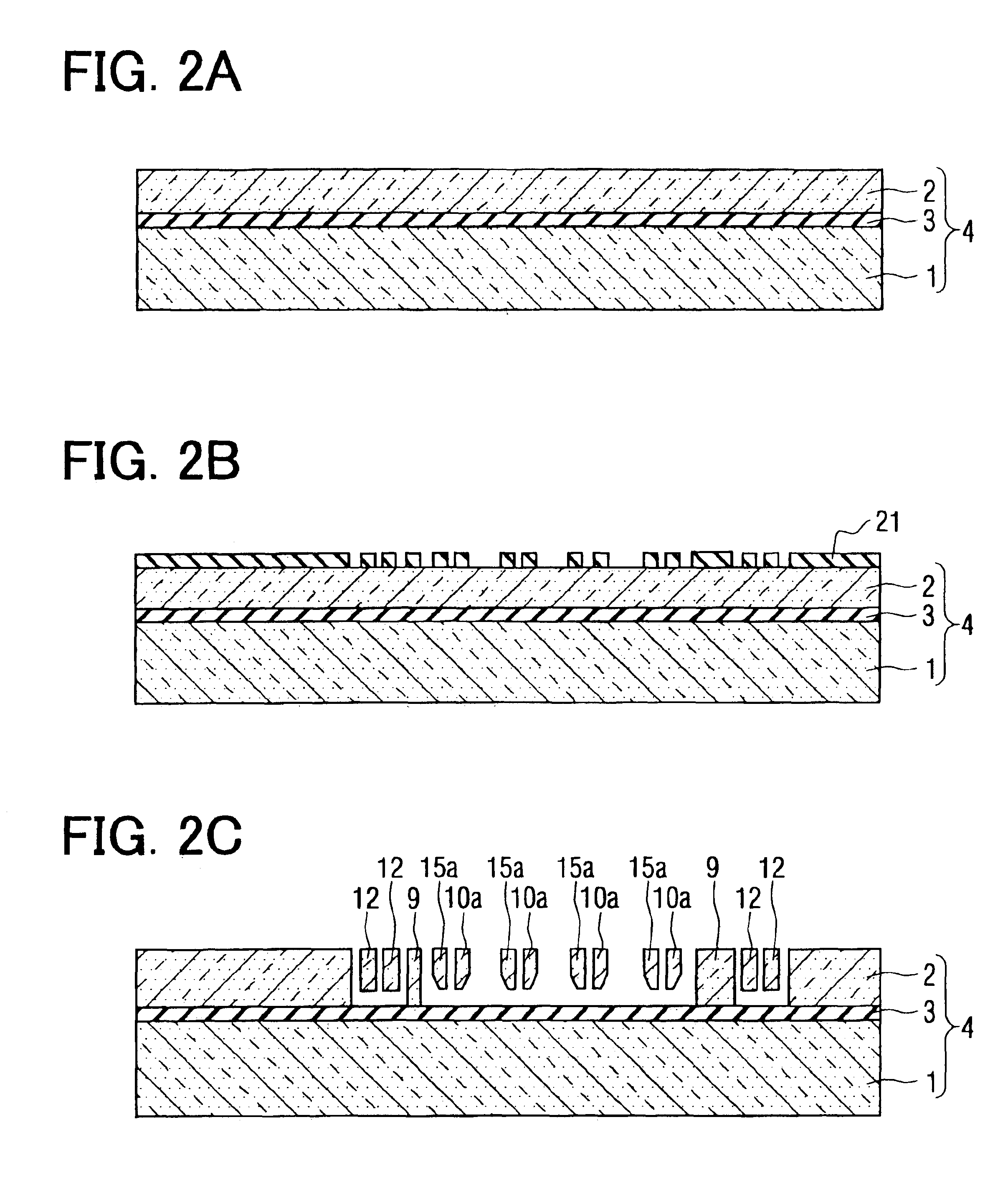
As shown in FIGS. 1A and 1B, a semiconductor acceleration sensor according to a first embodiment includes a substrate 4, which has a Silicon-On-Insulator (SOI) structure. The substrate 4 is composed of a semiconductor substrate 1, or a first semiconductor layer 1, a second semiconductor layer 2, and an insulating layer 3, which is a sacrificial layer made of, for example, silicon oxide. The semiconductor layers 1, 2 are made of single crystal silicon. The sensor of FIGS. 1A and 1B includes a sensing portion 5, which has been formed by well-known micromachining technology using semiconductor process technology.

As shown in FIG. 1A, the sensing portion 5 includes a movable unit 6, first and second fixed units 7, 8, and peripheral portion 9, which surrounds the movable unit 6 and the fixed units 7, 8. There are predetermined clearances between the movable unit 6, the fixed units 7, 8, and the peripheral portion 9 to insulate them from one another.

The movable unit 6 includes four first c...


PUM


Abstract

A capacitive dynamic quantity sensor includes a semiconductor substrate, a weight, a movable electrode, and two fixed electrodes. The weight is movably supported by the semiconductor substrate. The movable electrode is integrated with the weight. The fixed electrodes are stationarily supported by the semiconductor substrate. The fixed electrodes face the movable electrode to provide a narrow gap and a wide gap and form a detection part having a capacitance. The weight and the movable electrode are displaced relative to the fixed electrodes in response to a dynamic quantity to be detected such that one of the gaps increases while the other decreases. The dynamic quantity is detected on the basis of the variation in the capacitance. One of wide gap electrode surfaces, which define the wide gap, is smaller than narrow gap electrode surfaces, which define the narrow gap, to improve sensor sensitivity.

Description

BACKGROUND OF THE INVENTIONThe present invention relates to a capacitive dynamic quantity sensor, a method for manufacturing the capacitive dynamic quantity sensor, and a detector including the capacitive dynamic quantity sensor.For example, a capacitive semiconductor acceleration sensor shown in FIG. 7A is such a capacitive dynamic quantity sensor. As shown in FIGS. 7A and 7B, in the acceleration sensor, a weight 11 is supported by anchors 13, which are fixed to a semiconductor substrate 1, through springs 12. First and second comb-tooth-like movable electrodes 10a, 10b are integrated with the weight 11. As illustrated in FIG. 7A, first and second comb-tooth-like fixed electrodes 15a, 15b, which respectively face the first and second movable electrodes 10a, 10b, are supported at one ends thereof by first and second electrode wiring lines 16a, 16b. When acceleration is detected, predetermined voltages are applied between movable electrode pad 14 for the movable electrodes 10a, 10b a...

Claims


Application Information

Patent Timeline
Patent Type & Authority Patents(United States)
IPC IPC(8): G01P15/08G01P15/125G01R27/26H01L29/84
CPCG01P15/0802G01R27/2605G01P15/125G01P2015/0814
Inventor GOTO, KEISUKE
Owner DENSO CORP
Learn More