System, method and apparatus for the inspection of joints in a composite structure

a composite structure and joint technology, applied in the direction of instruments, specific gravity measurement, mechanical means, etc., can solve the problems of many drawbacks in the method, adversely affecting the composite structure, and difficult inspection of joints, etc., to achieve reliable detection of defects within joints, inexpensive manufacturing, and inexpensive implementation

Inactive Publication Date: 2005-02-01
THE BOEING CO
View PDF4 Cites 44 Cited by
  • Summary
  • Abstract
  • Description
  • Claims
  • Application Information

AI Technical Summary

Benefits of technology

In accordance with the present invention, an improved system and methods are provided for inspecting a joint in a composite structure. As such, the system and methods of the present invention can reliably detect defects within the joint. The system and methods of the present invention overcome the drawbacks of other automated inspection systems by inspecting t

Problems solved by technology

Flaws, such as cracks, voids, delaminations, or porosity can form in the joint region and adversely affect the composite structure.
Such joints are typically very difficult to inspect, however, particularly using traditional nondestructive inspection (NDI) methods.
While NDI methods including hand-operated UT transducers are adequate for detecting flaws in composite structures, such methods suffer from numerous drawbacks.
First, such methods are generally costly and time consuming as the operator is required to operate the hand-operated UT transducer during the entire process.
Second, such methods are operator dependent and, as such, are subject to potential operator errors.
Further, flaw indications are often subtle and, therefore, require tracking at multiple angles with complete coverage often difficult to ensure.
Third, such hand-operated inspection methods do not provide reviewable image data.
In this regard, no data is saved for subsequen

Method used


Image

  • System, method and apparatus for the inspection of joints in a composite structure
  • System, method and apparatus for the inspection of joints in a composite structure
  • System, method and apparatus for the inspection of joints in a composite structure

Examples


Embodiment Construction

The present invention now will be described more fully hereinafter with reference to the accompanying drawings, in which preferred embodiments of the invention are shown. This invention may, however, be embodied in many different forms and should not be construed as limited to the embodiments set forth herein; rather, these embodiments are provided so that this disclosure will be thorough and complete, and will fully convey the scope of the invention to those skilled in the art. Like numbers refer to like elements throughout.

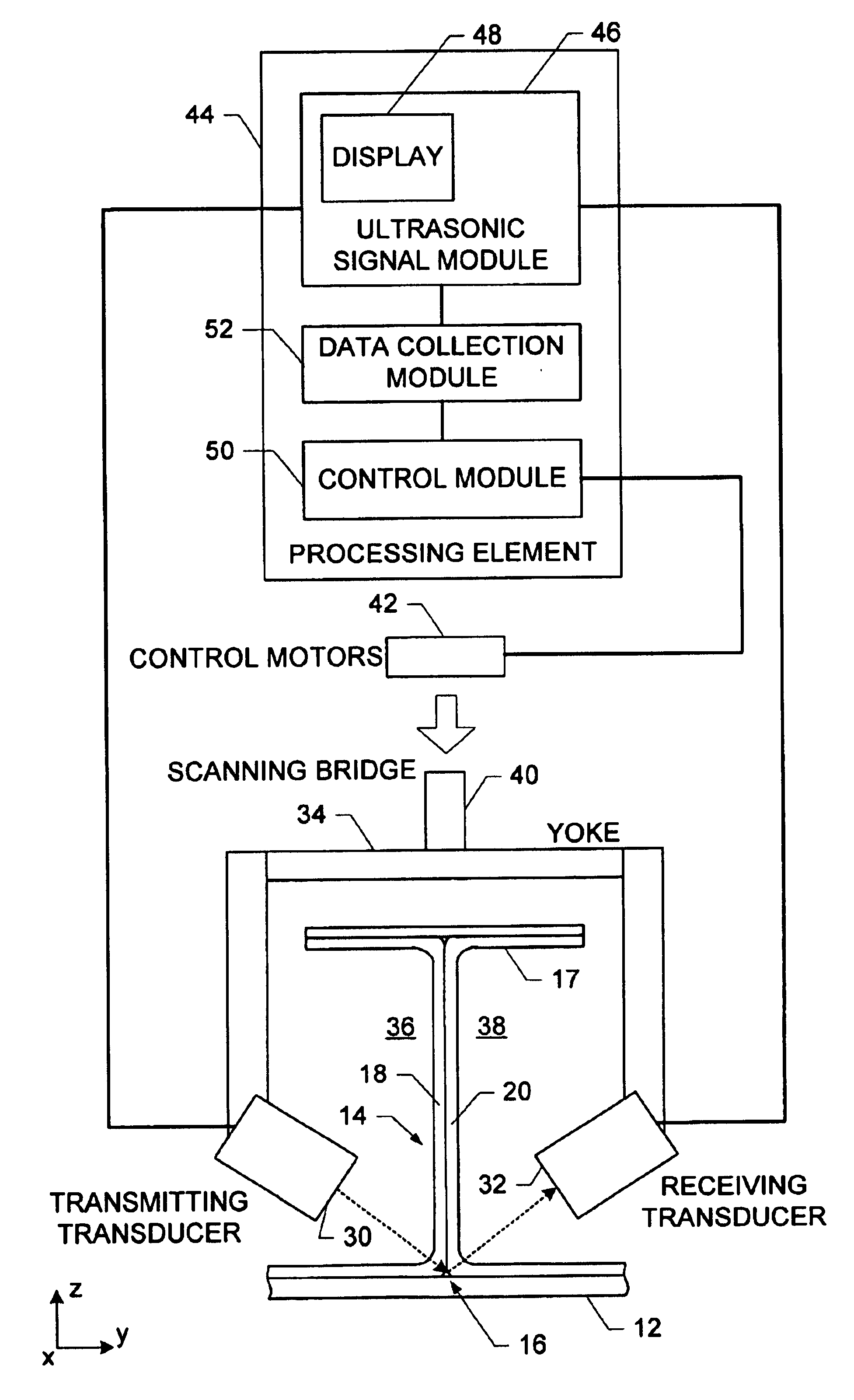
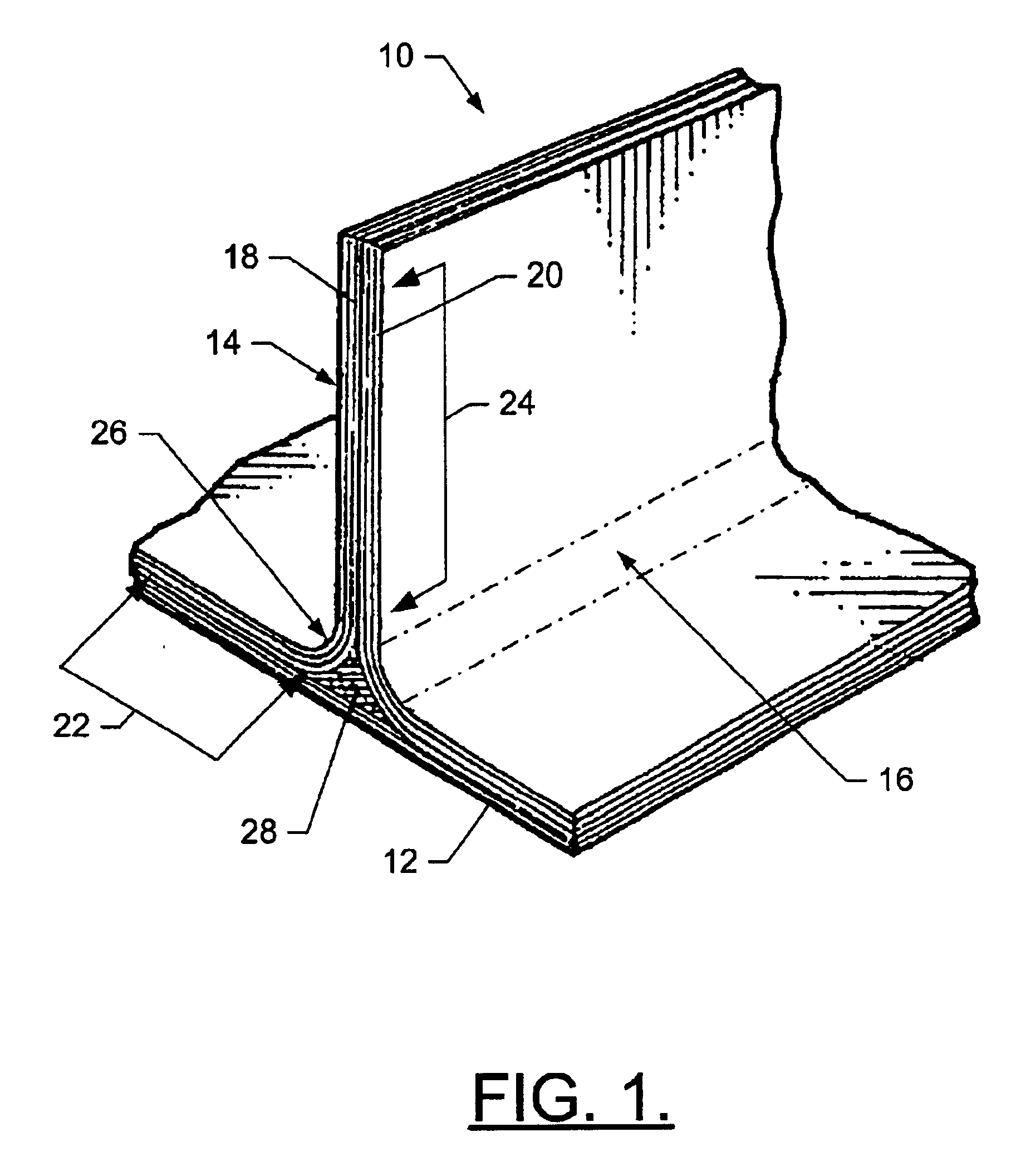
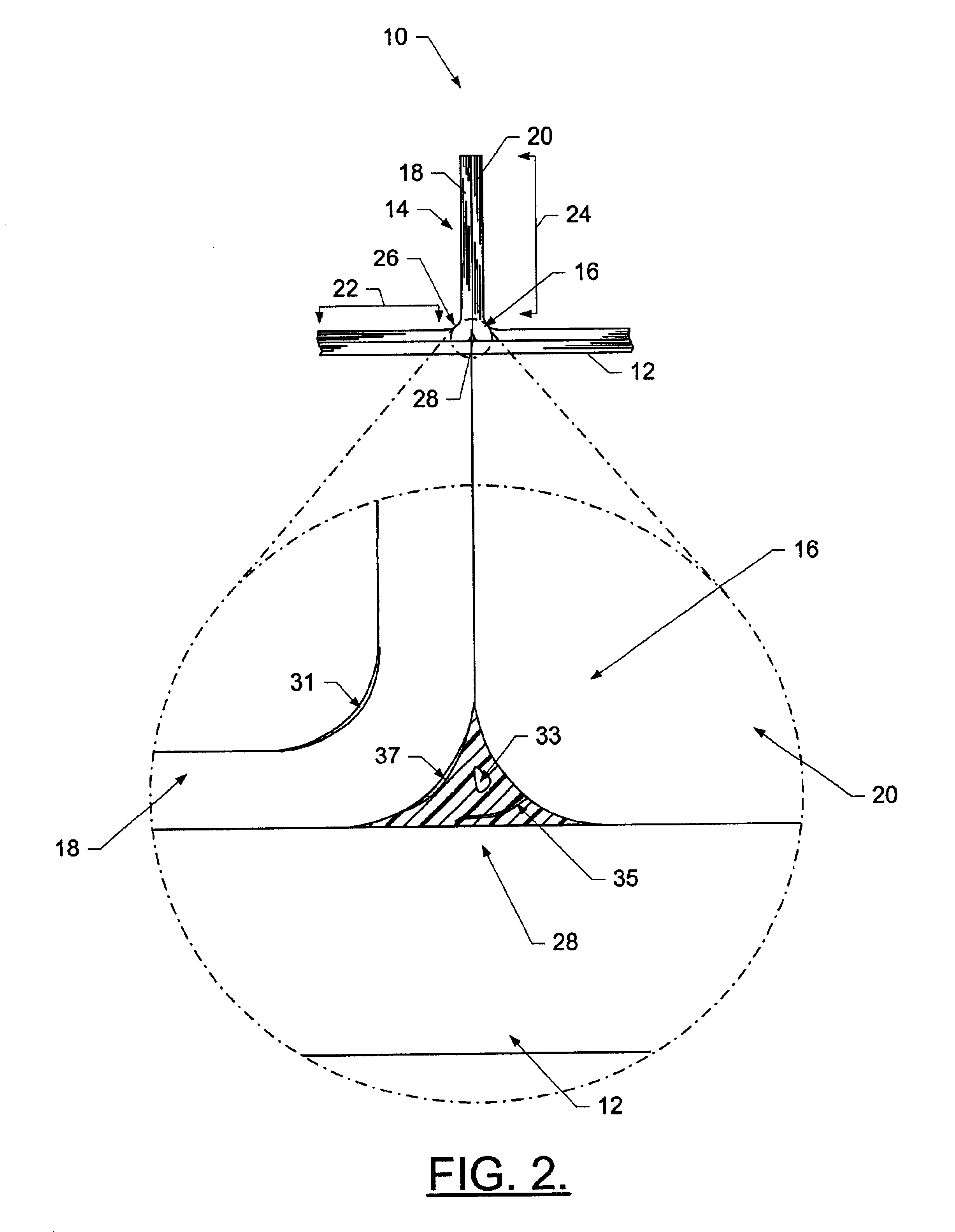
Referring to FIGS. 1 and 2, there is shown a reinforced composite structure generally indicated at 10. The composite structure generally comprises a first panel 12, such as skin, and a second panel 14, such as a web, that are connected thereby defining a joint generally indicated at 16. In instances where the first panel comprises a skin and the second panel comprises a web, the web would normally be jointed to an upper panel 17 or spar cap, as shown in FIGS. 3 ...


PUM


Abstract

A system for inspecting the joint of a composite structure includes a transmitting transceiver and a receiving transceiver, as well as a processing element. Typically, the composite structure includes first and second panels that are connected to define the joint, with the second panel extending outwardly from the first panel of the joint. Moreover, the composite structure includes a filler disposed at the joint. The transmitting transducer is disposed proximate an input side of the second panel and can transmit an ultrasonic signal into the second panel such that at least a portion of the signal reflects off of the first panel at the joint and exits an output side of the second panel. A receiving transducer disposed proximate the output side of the second panel can receive a reflected portion of the ultrasonic signal. And a processing element is capable of identifying a defect in the composite structure.

Description

FIELD OF THE INVENTIONThe present invention relates generally to systems and methods for inspecting joints in a composite structure and, more particularly, to systems and methods for inspecting joints in composite structures utilizing air-coupled transducers.BACKGROUND OF THE INVENTIONGenerally, composite structures are made up of multiple elements. And often, these elements intersect and are interconnected at joints. In this regard, the integrity of these joints is typically critical to the performance of the structure. One very common joint is the T-joint, where one plane of the composite ends at the surface of another. Another, less common joint, is the X-joint, in which two planes intersect one another. For design reasons, the intersections of these elements have some type of external radius (i.e., the intersection does not have sharp corners), and contain an internal filler material, sometimes referred to as a “noodle.” The quality of the noodle, its interface with the elements...

Claims


Application Information

Patent Timeline
IPC IPC(8): G01N29/11G01N29/04G01N29/44
CPCG01N29/11G01N29/2487G01N29/4427G01N2291/015G01N2291/0231G01N2291/0421G01N2291/267G01N2291/0428G01N2291/044G01N2291/048G01N2291/056G01N2291/102G01N2291/0422
Inventor GEORGESON, GARY E.
Owner THE BOEING CO
Why Eureka
Try Eureka