
Fire protection valve trim assembly system

Active Publication Date: 2005-02-01
VIKING
View PDF14 Cites 61 Cited by
  • Summary
  • Abstract
  • Description
  • Claims
  • Application Information

AI Technical Summary

Benefits of technology

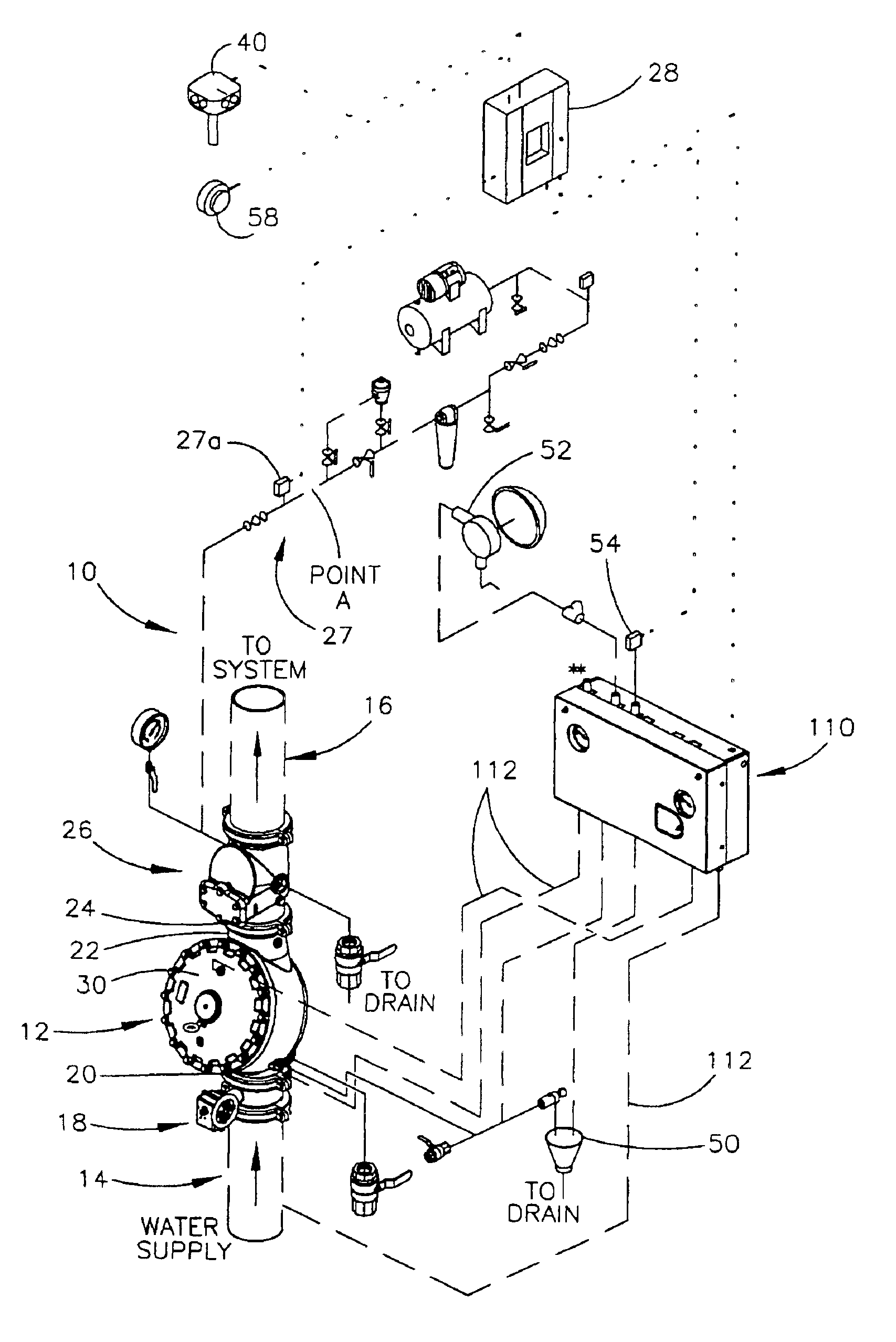
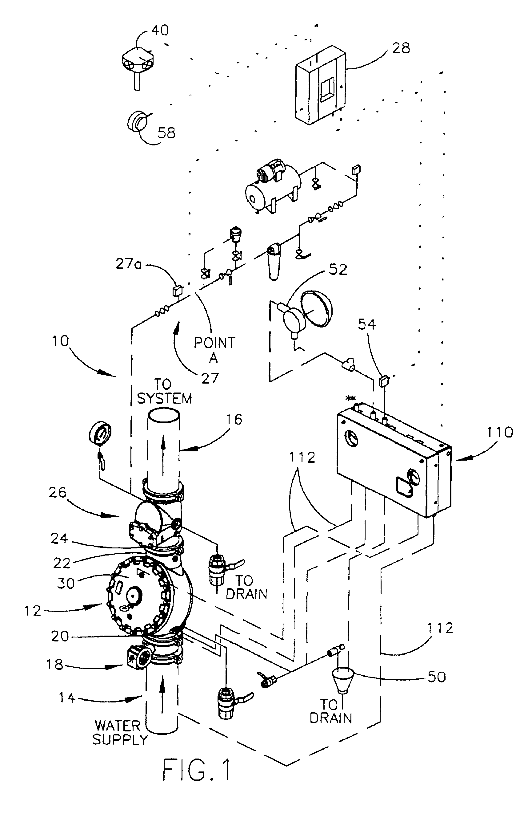
Accordingly, the present invention provides simplified trim piping assembly that can be assembled remotely from the site where the fire protection system is being installed and, further, can be tested prior to installation.
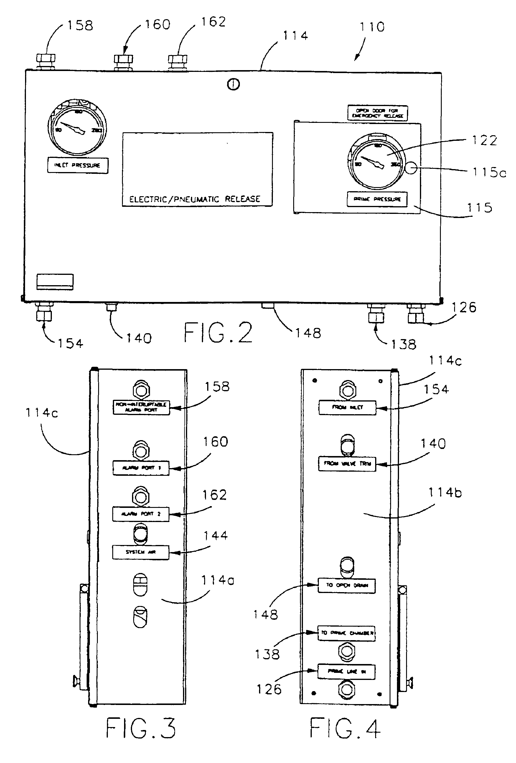
In one aspect, the mounting member comprises an enclosure with an enclosure wall. The inlet and outlet of the priming line and the discharge outlet are provided at the enclosure wall to thereby provide a compact trim assembly.

Problems solved by technology

However, the trim piping typically includes a significant number of components and, hence, is relatively complicated to install.
It has been found that given the complexity of the trim piping, components may be incorrectly located and / or installed in reverse orientation.
Thus, the trim system may not properly control the flow control valve requiring re-work or re-installation of the trim piping.

Method used


Image

  • Fire protection valve trim assembly system
  • Fire protection valve trim assembly system
  • Fire protection valve trim assembly system

Examples


first embodiment

Referring to FIGS. 11-14, trim assembly 310 includes an electric release for valve 12. As best seen in FIG. 14, trim assembly 310 includes an enclosure 314, similar to enclosure 114 and trim piping (and components) 316, similar to trim piping 116 of the In the illustrated embodiment, trim piping 316 eliminates the pneumatic actuator and, instead, provides an electric release of the priming pressure from priming chamber 30 of valve 12.

Trim piping 316 includes a priming line 324, which includes an inlet 326 that is in communication with the water supply 14, and an outlet 338 for communicating with priming chamber 30 of valve 12. Priming line 324 is similar to priming line 124 and includes a strainer 328, an orifice 330, and a check valve 332, which are all in series with pressurized shut-off valve 334. Pressurized shut-off valve 334 is normally open and directs the flow of priming fluid through outlet 338, which, as previously described, is in communication with priming chamber 30 of...

embodiment 610

Referring to FIGS. 21-24, another embodiment 610 of the trim assembly of the present invention is illustrated. Trim assembly 610 is similar to trim assembly 510 and includes many common components with trim piping 516 but includes an electric release for valve 412. Referring to FIG. 24, trim piping 616 of trim assembly 610 includes a priming line 624, which communicates with the water supply 414 through inlet 626 and delivers priming pressure to priming chamber 430 of valve 412 through outlet 638. Priming pressure is maintained in priming chamber 430 by check valve 632, normally closed solenoid 618, and by normally closed pressure operated release valve 643. For further details of the alarm connections, reference is made to the previous embodiments.

When a fire condition is detected by a detector (not shown but similar to detector 40), a control panel (similar to control panel 28) will open normally closed solenoid valve 618 to relieve the priming pressure from priming chamber 430 of...


PUM


Abstract

A trim assembly for a fire protection system valve includes a mounting member and a piping assembly supported by the mounting member. The piping assembly includes a priming line with an inlet for receiving priming fluid from a fire suppressant fluid supply line and an outlet for delivering priming fluid to a priming chamber of the fire protection system valve. The inlet and the outlet are provided at the mounting member. The piping assembly also includes a component, which responsive to a control signal and / or a pressure differential. The component redirects priming fluid away from the outlet of the priming line in response to the control signal and / or the pressure differential for controlling the delivering of priming fluid to the priming chamber of the fire protection system valve. The piping assembly further includes a discharge outlet, with the priming line discharging the priming fluid to the discharge outlet when the component directs priming fluid away from the outlet of the priming line, which is preferably provided at the mounting member.

Description

TECHNICAL FIELD AND BACKGROUND OF THE INVENTIONThe present invention relates to fire protection systems and, more particularly, to trim piping and components that control the operation of the main control valve of various fire protection systems.Fire protection systems come in several forms. For example, deluge fire protection systems totally flood the protected area with pressurized water, with the system designed to empty until the control valve is closed by a release system, such as a hydraulic, pneumatic, electric, or manual release system. These deluge systems are often used in areas where a fire may spread rapidly or in an area that contains combustible material or solutions or the like. Other fire protection systems cycle between actuated and non-actuated states and, in some cases, only deliver water to the affected area when actuated by a heat sensor.In some systems, the sprinkler system piping is filled with water prior to operation to permit a more rapid response. In other...

Claims


Application Information

Patent Timeline
IPC IPC(8): A62C35/68A62C35/58A62C35/64
CPCA62C35/68A62C35/64
Inventor JACKSON, ELDON D.FEENSTRA, SHAWN
Owner VIKING
Learn More