Accumulator

a technology of accumulators and cylinders, applied in the direction of brake components, brake cylinders, braking systems, etc., can solve the problem of reducing the vibrating sound of cylinders and braking, and it is expensive to reduce the vibrating sound a great deal, and achieve the effect of easy manufactur

Inactive Publication Date: 2005-02-01
NOK CORP
View PDF10 Cites 19 Cited by
  • Summary
  • Abstract
  • Description
  • Claims
  • Application Information

AI Technical Summary

Benefits of technology

The present invention exerts the following effects.
Because the accumulator 1 according to claim 1 of the present invention having the above-described structure has the chamber and the constriction within its housing, the aforementioned hydraulic noise can be suppressed by this chamber, constriction and vibration damping action. Further, because this chamber and constriction are not operating members unlike in the conventional technology but exist between the chamber forming member fixed inside the housing and the end wall portion of the housing provided with the fluid inlet, a bellows having as large a volume as in the conventional technology does not need to be employed. Therefore, the accumulator can be formed smaller.
Additionally, because in the accumulator according to claim 2 of the present invention, the chamber forming member is fixed to the housing not by welding unlike in the conventional technology but by non-welding means such as fitting, press-fitting, caulking, the quantity of its welded portions does not increase even if the chamber is provided in the housing. Therefore, the accumulator can be manufactured easily.
Further, because in the accumulator according to claim 3 of the present invention, the chamber forming member is fixed to the housing not by welding unlike in the conventional technology but by the convex loosening stopper engaging portion provided on the inner face of the housing, the quantity of its welded portions does not increase even if the chamber is provided within the housing. Therefore, the accumulator can be manufactured easily.
Further, because in the accumulator according to claim 4 of the present invention, the chamber forming member is fixed to the housing not by welding unlike in the conventional technology but by such a loosening stoppage member as the stopper ring fixed on the inner face of the housing, the quantity of its welded portions does not increase even if the chamber is provided within the housing. Therefore, the accumulator can be manufacture easily.
Further, because in the accumulator according to claim 5 of the present invention, the chamber forming member is fixed to the housing not by welding unlike in the conventional technology but by inserting the chamber forming member into the outer periphery of the insertion fixing portion provided on the housing, the quantity of its welded portions does not increase even if the chamber is provided within the housing. Therefore, the accumulator can be manufactured easily.

Problems solved by technology

A conventional accumulator cannot suppress this hydraulic vibration sound but cope with this sound by providing its hydraulic circuit with a complicated structure.
Therefore, it costs a great deal to reduce this vibrating sound.
However, because the chamber 53 and the constriction 54 are provided inside an end member (called bellows cap also) which constitutes an operating member 5 of the accumulator 51 with a bellows 56, the bellows 56 internally filled with gas needs to have a large volume and therefore, there is such an inconvenient problem that the accumulator 51 has been enlarged.

Method used


Image

  • Accumulator
  • Accumulator
  • Accumulator

Examples


first embodiment

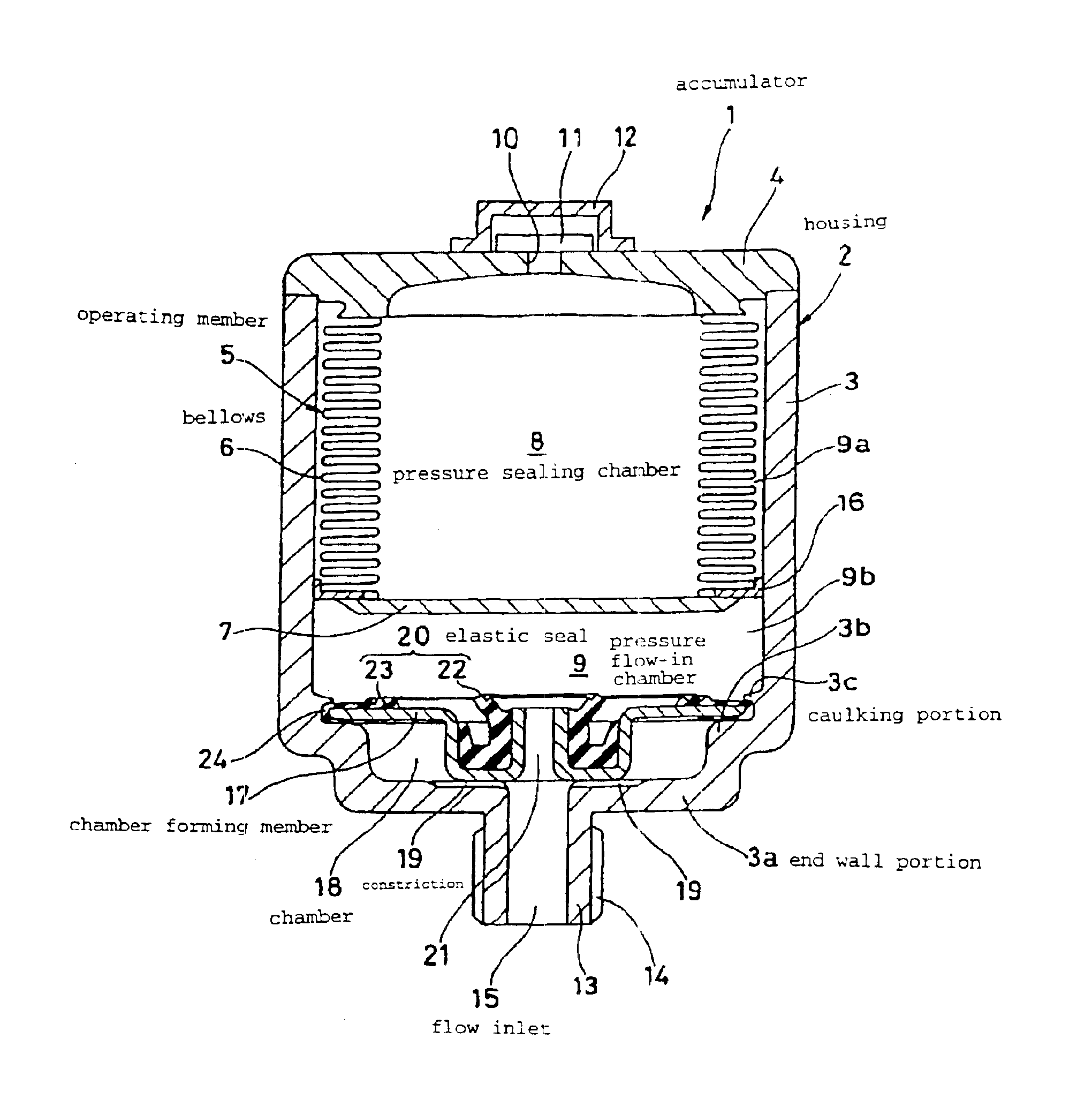
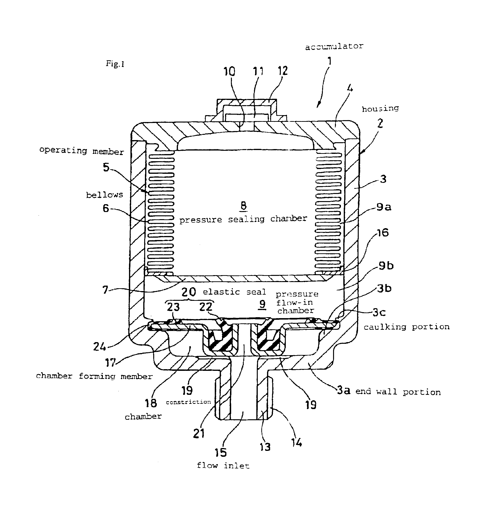
FIG. 1 shows a section of the accumulator 1 according to a first embodiment of the present invention and FIG. 2 shows an enlargement diagram of its main portion.

The accumulator 1 of this embodiment is a metallic bellows type accumulator and has the following structure.

First, a housing 2 is provided by fixing a lid member (called gas end cover also) to an open end portion of a bottomed cylindrical shell 3 (by carbon dioxide laser welding) and an operating member 5 having a bellows 6 and an end member (called bellows cap also) 7 is accommodated inside this housing 2.

An end portion of the bellows 6 is fixed to the lid member 4 (by TIG welding) while the other end thereof is fixed to the end member 7 (by TIG welding). The interior of the housing 2 is partitioned by the bellows 6 and the end member 7 to a pressure sealing chamber (called gas chamber also) 8 inside the bellows 6 and the end member 7 and a pressure flow-in chamber (called liquid chamber or hydraulic chamber also) 9 outside...

second embodiment

A third cylindrical portion 17f is formed integrally on an outer peripheral end portion of the outer flat portion 17d of the chamber forming member 17 of the first embodiment such that it is directed toward the end wall portion 3a. The chamber forming member 17 is press-fit through this third cylindrical portion 17f against the end wall portion 3a of the shell 3 of the housing 2 and caulked by the shell 3. The inner peripheral seal 22 and the outer peripheral seal 23 are made continuous by the film portion 25 formed integrally between the both seals 22 and 23. According to this embodiment, because the outer peripheral portion of the chamber forming member 17 is positioned and held with respect to the shell 3 by the third cylindrical portion 17f, the step portion 3b does not need to be provided in the end wall portion 3a of the shell 3 unlike in the first embodiment.

third embodiment

FIG. 4 shows the section of an accumulator 1 according to the third embodiment of the present invention and FIG. 5 shows an enlargement diagram of its major components.

The accumulator 1 of this embodiment is a metallic bellows type accumulator, which has the following structure.

First, a housing 2 is provided by fixing (welding) a lid member (called gas end cover also) 4 to the open end portion 3a of a bottomed cylindrical shell 3 and further fixing a port member (called oil port also) 31 to the center of the flat face of the end wall portion 3a of the shell. An operating member 5 composed of a bellows holder 32, a bellows 6 and an end member (called bellows cap also) 7 is accommodated within this housing 2.

The bellows holder 32 is fixed (welded) to inner faces of the shell 3 and the lid member 4 and an end portion of the bellows 6 is fixed (welded) to the bellows holder 32 while the other end thereof is fixed (welded) to the end member 7. Consequently, the interior of the housing 2 ...


PUM


Abstract

An accumulator (1) capable of suppressing a hydraulic pressure vibrating noise in the range of a sealed gas pressure or below and being reduced in size, wherein an operating member (5) having a bellows (6) is disposed in a housing (2) to partition the inside of the housing (2) into a pressure sealed chamber (8) and a pressure inflow chamber (9) and a fluid inlet (15) for leading pressure fluid from a system side to the pressure inflow chamber (9) is formed in the end wall part (3a) of the housing (2), a chamber forming member (17) is fixed to the inside of the housing (2), and a chamber (18) and a choke (19) are provided between the chamber forming member (17) and the end will part (3a) of the housing (2).

Description

TECHNICAL FIELD PERTINENT TO THE INVENTIONThe present invention relates to an accumulator used as a pressure accumulating apparatus, a pulse damping apparatus or the like.PRIOR ARTFor example, a hydraulic system of the brake or suspension related mechanism of a vehicle (passenger car, truck and the like) has adopted a metallic accumulator for the purpose of pressure accumulation (compensation for pump capacity or the like), pulse damping or the like. Usually, the region in which this accumulator functions is a hydraulic range above the point A in a graph of FIG. 17. Therefore, the hydraulic range below the point A is equivalent to a condition in which no accumulator exists.As a problem for the vehicle which often occurs in the range below the point A, occurrence of hydraulic noise due to system resonance or the like by pump exhausting vibration can be mentioned. A conventional accumulator cannot suppress this hydraulic vibration sound but cope with this sound by providing its hydrau...

Claims


Application Information

Patent Timeline
Patent Type & Authority Patents(United States)
IPC IPC(8): F15B1/00F15B1/24F15B1/22F15B1/10F16L55/04F16L55/053F15B1/08
CPCF15B1/103F15B1/22F16L55/053F15B2201/205F15B2201/3158F15B2201/605F15B2201/3153
Inventor YUDA, AKIOKITAHARA, TOSHIAKI
Owner NOK CORP
Why Eureka
Try Eureka