
Battery, a process for producing the battery, a process for producing a battery case, and a battery pack

a battery and process technology, applied in the direction of sustainable manufacturing/processing, nickel accumulators, cell components, etc., can solve the problems of poor space efficiency, increase production costs, and difficulty in the production step of square pillar batteries, so as to improve space efficiency and improve productivity.

Inactive Publication Date: 2005-02-01
PANASONIC CORP
View PDF17 Cites 26 Cited by
  • Summary
  • Abstract
  • Description
  • Claims
  • Application Information

AI Technical Summary

Benefits of technology

[0007]The object of the present invention is, overcoming the above-mentioned problems, to provide a battery which is improved in productivity and improved in space efficiency when constructed into a battery pack or when mounted on appliances.

Problems solved by technology

Cylindrical pillar batteries, when used to construct a battery pack housing several batteries, give a poor space efficiency.
On the other hand, square pillar batteries have a difficulty in the production step thereof though they give a high space efficiency in the pack.
That is, the met hod used in laser-welding processing for sealing requires a controlling means for stabilizing the laser, additionally causing increase in production cost.
In this method, however, strain develops at the corner part and hence the tightness of sealing is poorer than when a cylindrical pillar battery is sealed by caulking.

Method used


Image

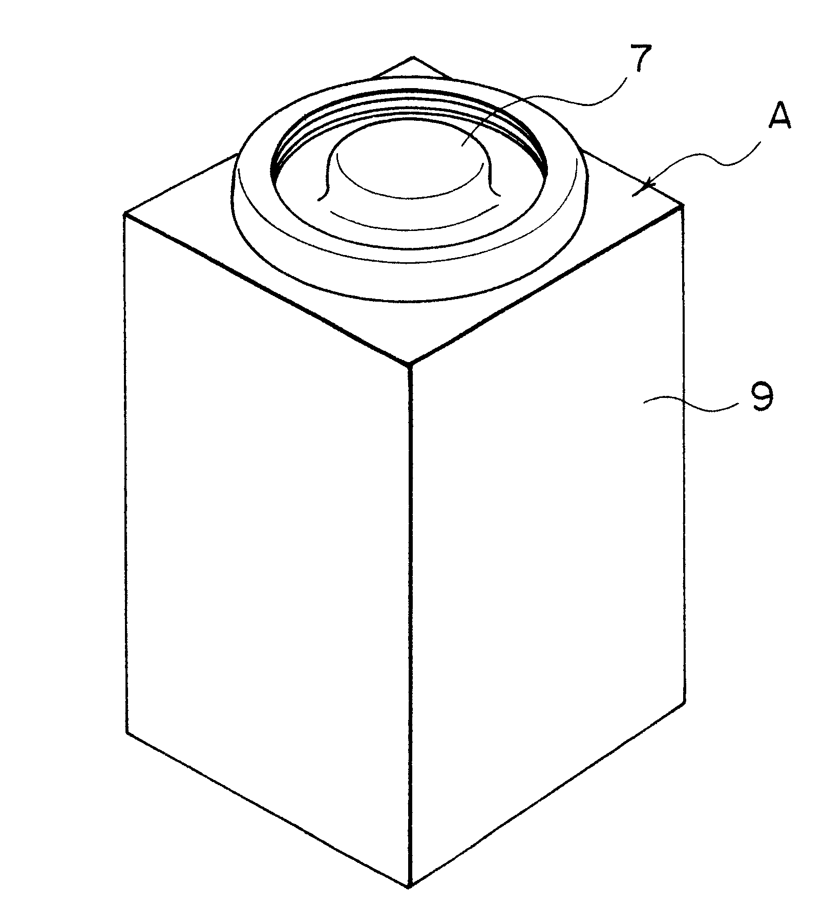
  • Battery, a process for producing the battery, a process for producing a battery case, and a battery pack
  • Battery, a process for producing the battery, a process for producing a battery case, and a battery pack
  • Battery, a process for producing the battery, a process for producing a battery case, and a battery pack

Examples


example 1

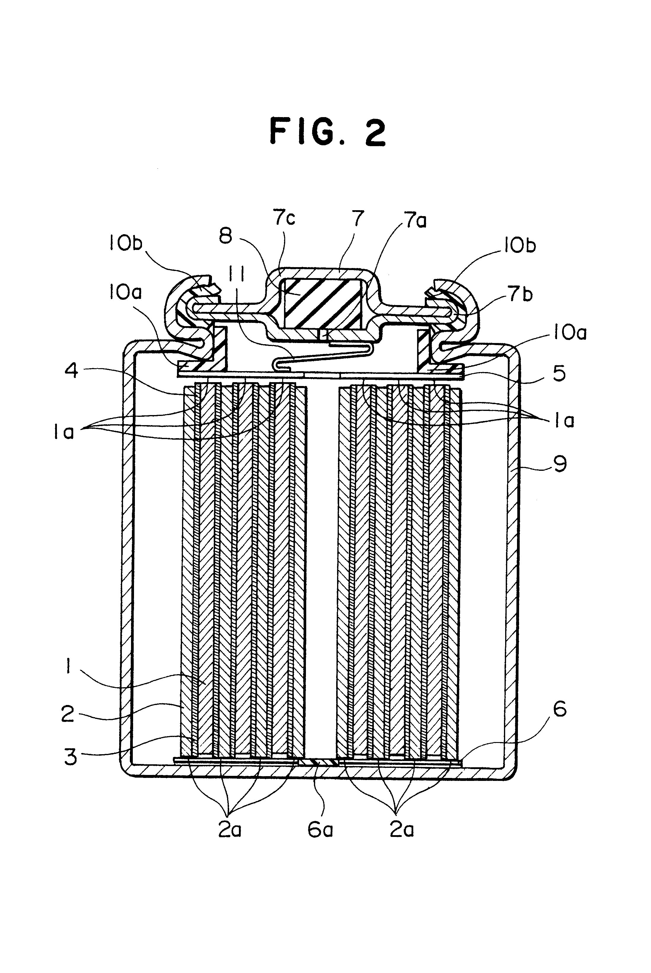
[0050]An electric element 4 was constructed by interposing a separator 3 between a belt-shaped positive electrode 1 and a belt-shaped negative electrode 2 and spirally coiling them with the terminal edge 1a of the positive electrode 1 being projected upwards and the terminal edge 2a of the negative electrode 2 being projected downwards.

[0051]An upper current collector 5 having a hole at the center was resistance-welded to the terminal edge 1a of the positive electrode 1 of the electric element 4, and a lower current collector 6 having a tongue 6a was resistance-welded to the terminal edge 2a of the negative electrode 2.

[0052]A sealing plate 7 was constructed by arraying a filter 7b having a valve-opening 7a and a rubber valve body 8, placing a cap-formed terminal 7c thereon, and resistance-welding the filter 7b with the cap-formed terminal 7c.

[0053]A metal case 9 for batteries was made by rotating a square barrel-shaped case while pushing it up from the underside, putting its openi...

example 2

[0061]In Example 1, description was given of an example wherein an electric element was inserted in a case of which the shape of the upper part had been already formed. In the present Example, description is given of battery production steps wherein the electric element is inserted first and then the shape of the case is formed with reference to the schematic diagram shown in FIG. 5. In the following description, some of the reference numerals used are not shown in FIG. 5.

[0062]Reference is made to FIG. 5. An electric element 4 was constructed by interposing a separator 3 between a belt-shaped positive electrode 1 and a belt-shaped negative electrode 2 and spirally coiling them with the terminal edge of the positive electrode 1 being projected upwards and the terminal edge of the negative electrode 2 being projected downwards. To the terminal edge 1a of the positive electrode 1 of the electric element 4 constructed above were resistance-welded an upper current collector 5 having a h...

example 3

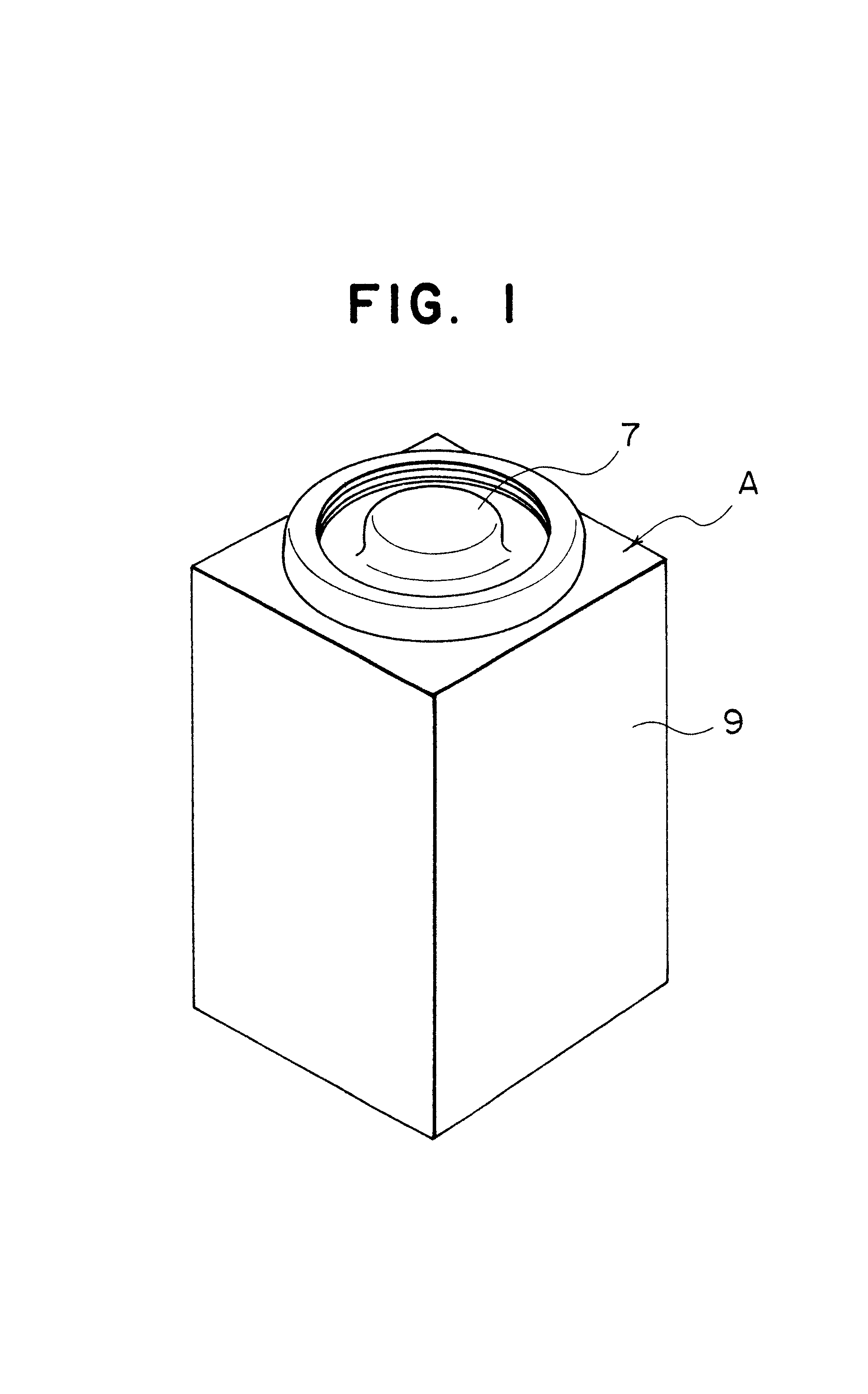
[0067]A battery C was made in the same manner as in Example 2 but by using a hexagonal barrel case. The perspective view of the battery C is shown in FIG. 6. A plan view of a battery pack for power tools constructed by closely packing the battery C is shown in FIG. 7. As a Comparative Example, a battery pack employing the cylindrical pillar battery B of Comparative Example hitherto used is also shown in FIG. 7.

[0068]It can be seen that the space utilization ratio in the battery pack is higher in the battery pack using the battery of the present invention of which the upper part is circular and the lower part is hexagonal than in the pack using the battery B of Comparative Example and that the battery of this invention thus makes it possible to utilize the space in the battery pack with higher efficiency.


PUM

PropertyMeasurementUnit
Electrical conductoraaaaaaaaaa
Electric propertiesaaaaaaaaaa

Abstract

The present invention relates to a battery using a case of which the section of the lower part containing an electric element is square or hexagonal and the section of the upper part containing a sealing plate is circular or elliptic. By virtue of the shape of the lower part the space efficiency of the battery pack is enhanced and by virtue of the shape of the upper part the productivity of the battery is improved. Further, preferably, the corners of the lower part of the case are rounded or chamferred, whereby the temperature rise in the battery pack is suppressed.

Description

TECHNICAL FIELD[0002]The present invention relates to a battery, a process for producing the battery, a process for producing a battery case, and a battery pack.BACKGROUND ART[0003]In recent years, with the advance of various portable appliances, great importance has been being placed to the development of batteries as one of the important key devices thereof. In particular, rechargeable secondary batteries, which are used in a variety of appliances including portable telephones, notebook-sized personal computers and further, in recent years, hybrid electric automobiles have been increasingly requested on the market.[0004]The shape of batteries generally used at present is a cylindrical pillar or a square pillar.[0005]Cylindrical pillar batteries, when used to construct a battery pack housing several batteries, give a poor space efficiency. On the other hand, square pillar batteries have a difficulty in the production step thereof though they give a high space efficiency in the pack...

Claims


Application Information

Patent Timeline
IPC IPC(8): H01M2/04H01M2/10H01M10/42H01M2/02H01M10/50H01M6/44H01M6/42H01M10/34H01M10/24H01M10/30H01M6/04H01M10/40H01M10/36H01M6/10H01M10/05H01M50/209
CPCH01M2/0417H01M2/1055H01M2/1066H01M6/44H01M10/5004H01M10/5012H01M10/5014H01M10/5028H01M10/5036H01M10/5046H01M10/5048H01M10/5053H01M10/5055H01M2/023H01M2/0217Y10T29/4911H01M6/10H01M10/05H01M10/30H01M10/345H01M10/5016H01M10/504Y10T29/53135Y10T29/49108H01M10/625H01M10/653H01M10/64H01M10/6551H01M10/6552H01M10/6555H01M10/623H01M10/6554H01M10/6235H01M10/651H01M10/613Y02E60/10H01M50/56H01M50/103H01M50/154H01M50/213H01M50/209Y02P70/50
Inventor KASAHARA, HIDEKIKATSUMOTO, MASUMIMIYAHISA, MASAHARUBOKI, YOSHIHIRO
Owner PANASONIC CORP
Learn More