Precision multiple electrode ion mirror

a technology of ion mirrors and ion mirrors, which is applied in the manufacture of electrode systems, electric discharge tubes/lamps, and separation processes, etc., can solve the problems of ion mirror assembly expansion or contraction along its axis, cumbersome errors can accumulate, and involve significant part and labor costs, so as to improve parallelism and improve parallelism

Inactive Publication Date: 2005-02-01
AGILENT TECH INC
View PDF10 Cites 18 Cited by
  • Summary
  • Abstract
  • Description
  • Claims
  • Application Information

AI Technical Summary

Benefits of technology

It is therefore an object of the present invention to provide an ion mirror having improved parallelism between mirror elements and also to provide a method of constructing such an ion mirror with improved parallelism.

Problems solved by technology

In particular, systematic errors in the sizes of the electrode plate elements can cause an ion mirror assembly to expand or contract along its axis.
Furthermore, cumulative errors can build up if the insulating spacers are not precisely dimensioned. FIG. 3 schematically illustrates the effect that such systematic errors and other commonly occurring inaccuracies, such as misalignment, can have on the contour of equipotential lines within the ion conduit region of an ion mirror.
However, these operations involve significant part and labor costs.

Method used


Image

  • Precision multiple electrode ion mirror
  • Precision multiple electrode ion mirror
  • Precision multiple electrode ion mirror

Examples


second embodiment

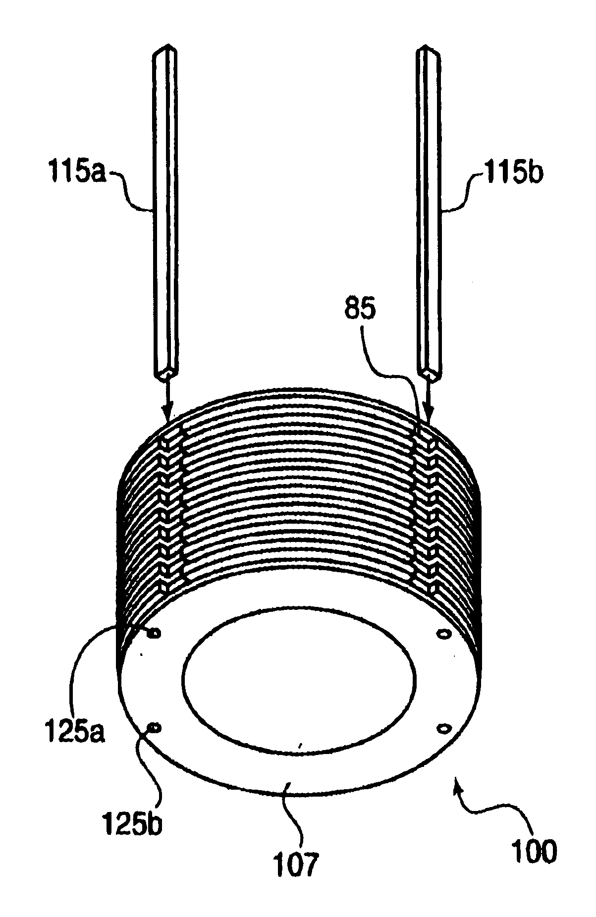
Alternatively, according to constructing a precision turned ion mirror according to the present invention, a number of individual electrode plate elements are made by separate turning operations and detached from one or more workpieces. The electrode plate elements are arranged sequentially in a stack, with each of electrode plate elements separated from adjacent elements using reusable precision spacers which keep the individual electrode plate elements in parallel alignment in the stack arrangement. After being stacked, the individual electrode plate elements may be drilled, bored, and / or machined to remove their respective central portions. This can be performed by a single EDM operation. Boring the plate elements after aligning them in a stack improves the uniformity and alignment of the bored sections among the elements. With the precision spacers still in place, axially extending insulating rods that run along the entire axial length of the stack are then fixed to the electrod...


PUM

PropertyMeasurementUnit
widthaaaaaaaaaa
lengthaaaaaaaaaa
diameteraaaaaaaaaa

Abstract

A method of constructing an ion mirror having an axial axis which includes arranging electrode plate elements in parallel alignment along the axial axis and attaching a rigid structure to all of the electrode plate elements with adhesive, thereby fixing the electrode plate elements in their respective axial positions and parallel alignment. In an embodiment of the method, the electrode plate elements are arranged in parallel alignment by turning the electrode plate elements from a single workpiece. In an alternative embodiment, the electron plate elements are arranged in parallel alignment by stacking the electrode plate elements using precisely dimensioned spacers, and the spacers are then removed after attachment of the rigid structure.

Description

FIELD OF THE INVENTIONThe present invention relates to mass spectrometer systems, and more particularly, but without limitation, relates to a precision turned multiple electrode ion mirror used to manipulate ion trajectories in mass spectrometer systems.BACKGROUND INFORMATIONIon mirrors, or reflectrons, are components used in mass spectrometer systems to reverse or redirect the trajectory of ions as they travel toward a detector within a mass analyzer. In particular, ion mirrors are often used in Time-of-Flight (TOF) mass spectrometers where they are placed at the end of a drift region. FIG. 1 depicts a conventional ion mirror 5 with top portions cut away for illustrative purposes. A series of electrically conductive electrode plate elements 10, which can vary in number, are arranged spaced apart in the axial direction by insulating spacer elements 15. As shown, the electrode plate elements 10 are configured as rectangular rings enclosing a central ion conduit region 20 through whic...

Claims


Application Information

Patent Timeline
Patent Type & Authority Patents(United States)
IPC IPC(8): H01J49/40H01J49/34
CPCH01J49/40Y10T29/49117H01J2237/0535H01J49/405
Inventor BERTSCH, JAMES L.
Owner AGILENT TECH INC
Why Eureka
Try Eureka