
Coil on plug capacitive signal amplification and method of determining burn-time

a capacitive signal and coil technology, applied in the direction of engine ignition, spark plug ignition, machines/engines, etc., can solve the problems of preventing the application of the conventional technique implemented in fig and the difficulty of any one sensor to find universal applicability

Inactive Publication Date: 2005-02-01
NOKIA CORP +1
View PDF9 Cites 19 Cited by
  • Summary
  • Abstract
  • Description
  • Claims
  • Application Information

AI Technical Summary

Benefits of technology

The patent describes a device and method for testing the ignition of a coil-on plug device. The device includes a capacitive sensor that detects an electric field generated during a firing event and generates an output signal. This signal is then amplified and processed to determine the ignition time of the device. The method involves placing the sensor near the device and detecting the electric field during a firing section. The device can also be tested for problems by comparing the results of two devices. The technical effects of this invention include improved accuracy in detecting ignition and identifying problems with the coil-on plug device.

Problems solved by technology

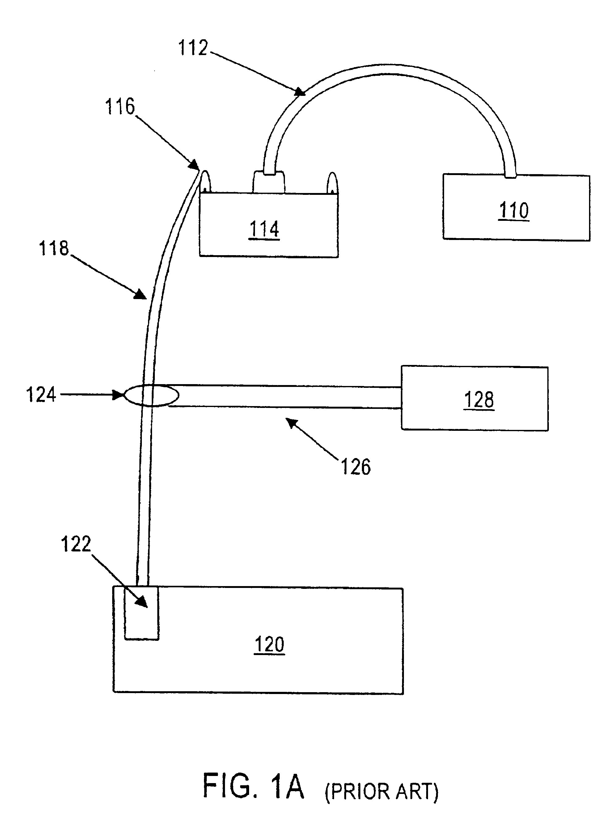
This arrangement prevents application of the conventional technique implemented in FIG. 1a, since the high secondary voltage conductor is not as easily accessed as the wire 118 of FIG. 1a.
Despite the advancements realized by present coil-on plug signal detection devices, the sheer variety of ignition coil configurations make it difficult for any one sensor to find universal applicability.

Method used


Image

  • Coil on plug capacitive signal amplification and method of determining burn-time
  • Coil on plug capacitive signal amplification and method of determining burn-time
  • Coil on plug capacitive signal amplification and method of determining burn-time

Examples


Embodiment Construction

FIGS. 2a and 2b illustrate, respectively, a typical primary ignition waveform and secondary ignition waveform as a function of time. The waveforms have three basic sections labeled Firing Section, Intermediate Section, and Dwell Section.

Common reference numerals are used in FIGS. 2a and 2b to represent common events occurring in both the primary and secondary waveforms. At the start S of the waveform, no current flows in the primary ignition circuit. Battery or charging system voltage available at this point generally ranges from approximately 12-15 volts, but is typically between about 12-14 volts. At 210, the primary switching device turns on the primary current to start the “dwell” or “charge” section. At 220, current flows through the primary circuit, establishing a magnetic field in the ignition coil windings. A rise in voltage occurs along 230 indicating that coil saturation is occurring and, on ignition systems that use coil saturation to control coil current, a current hump ...


PUM


Abstract

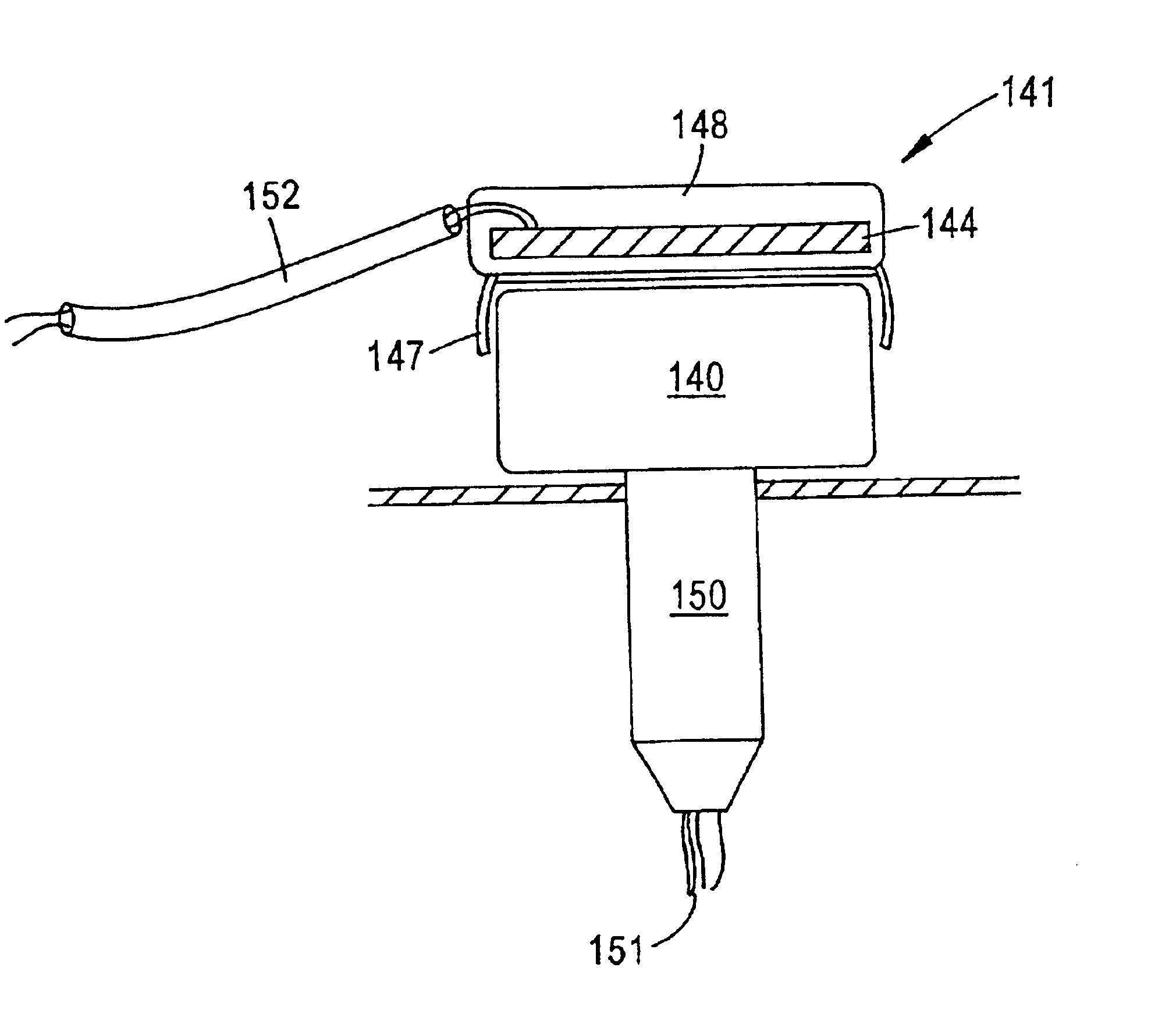
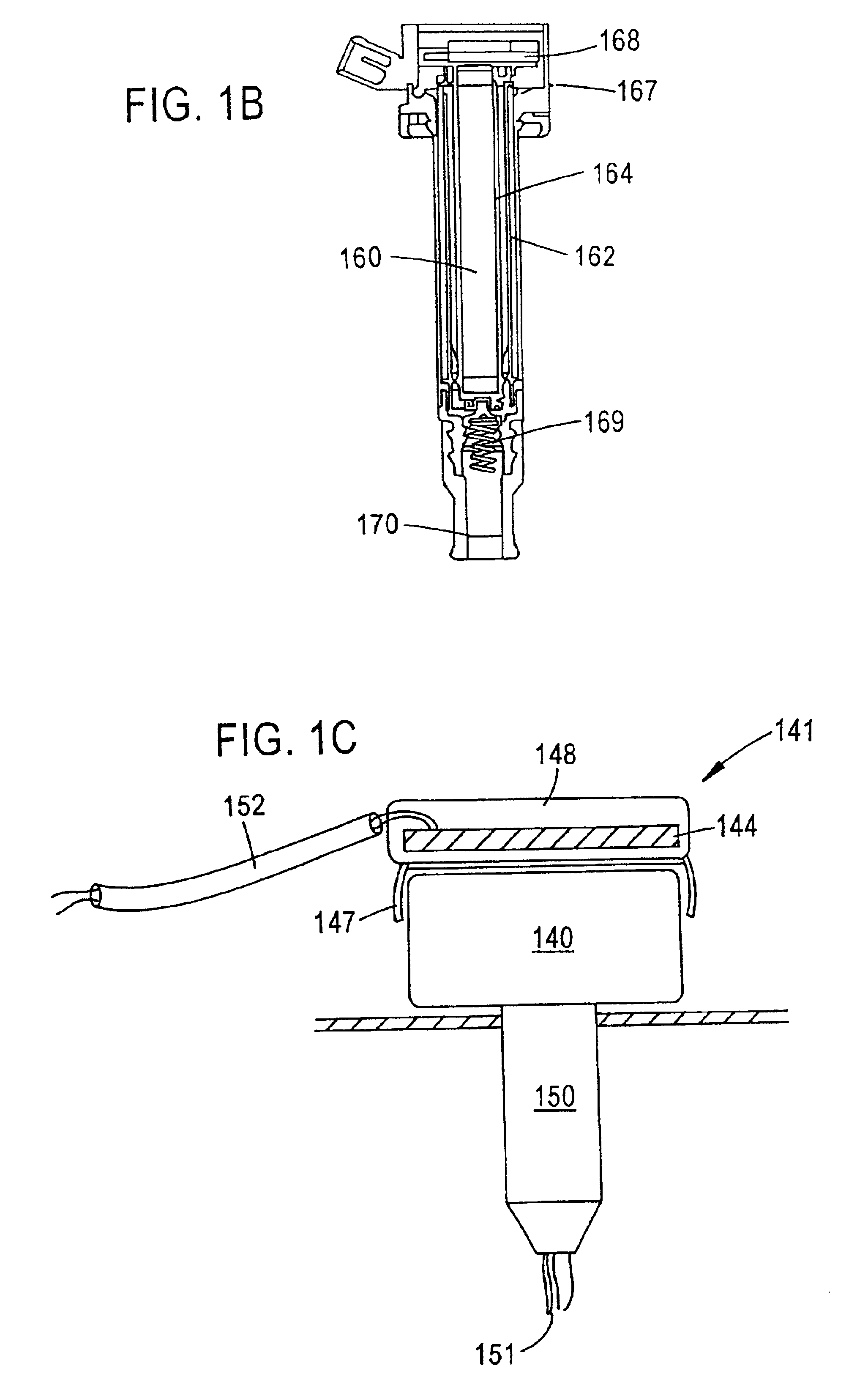
A coil-on plug testing apparatus for detecting a weak field output by a shielded coil-on plug ignition and generating an output signal representing an ignition signal includes a capacitive sensor attachable to a coil-on-plug device for detecting an electric field generated by the shielded coil-on plug device during a firing event and generating and outputting a voltage in response thereto. A signal processing circuit electrically coupled to the capacitive sensor is configured to generate an output signal in response to variations in the voltage output by the capacitive sensor in response to a detected electric field. The signal processing circuit comprises an amplifier configured to amplify an output voltage of the capacitive sensor.

Description

TECHNICAL FIELDThe disclosure relates to engine analyzers for internal combustion engine direct ignition systems inclusive of coil-on plug or coil-over plug ignitions and, more particularly, to engine analyzers employing ignition signal pickups to detect ignition waveforms in direct ignition systems. The disclosure has particular applicability to automotive engine analysis in which secondary ignition waveforms and the numerical value of segments of such waveforms are displayed for technician evaluation.BACKGROUND DISCUSSIONEngine analyzers provide mechanics with a tool for accurately checking the performance of the ignition system as a measure of the overall engine performance. Signal detectors (“test probes”) are widely used in diagnosing defects and anomalies in internal combustion engines. A test probe is, for example, placed adjacent to a test point such as a ignition coil or ignition wire, and the test probe communicates the signal back to a motor vehicle diagnostic apparatus. ...

Claims


Application Information

Patent Timeline
Patent Type & Authority Patents(United States)
IPC IPC(8): F02P13/00F02P17/12F02P17/00F02P17/08
CPCF02P13/00F02P17/12F02P17/00F02P2017/006
Inventor MCQUEENEY, KENNETH A.BRYANT, ROBERT R.
Owner NOKIA CORP
Learn More