Liquid crystal display device

Inactive Publication Date: 2005-02-01
SHARP KK
View PDF8 Cites 10 Cited by
  • Summary
  • Abstract
  • Description
  • Claims
  • Application Information

AI Technical Summary

Benefits of technology

[0051]Each of the first region and the third region is provided for the purpose of inclining the electric field along the boundary between that region and the second region, i.e., to obtain an orientation-regulating force therebetween. The second region is a region in which the liquid crystal molecules are oriented substantially uniformly due to this orientation-regulating force, thereby obtaining a substantially uniform amount of transmitted light across the region. Generally, in a liquid crystal display device, if one employs a structure with which a uniform amount of transmitted light can be obtained across the entire picture element region (e.g., a TN type liquid crystal display device), it is possible to obtain the maximum light efficiency (the highest transmittance) for the picture element region as a whole (or for the display region of the liquid crystal display device as a whole). Thus, in the case of a liquid crystal display device of the present invention, it is preferred in terms of the light efficiency that the area of the entire picture element region which is occupied by the second region (where a uniform amount of transmitted light can be obtained) is increased as much as possible, thereby increasing the light efficiency. Accordingly, in order to increase the light efficiency, it is preferred that the area of the entire picture element region which is occupied by the first and third regions is reduced as much as possible within such an extent that a desired orientation-regulating force can be obtained so as to increase as much as possible the area occupied by the second region.
[0052]It is possible to reduce the area of a picture element region occupied by the first region and the third region by arranging the plurality of orientation-regulating regions so that the orientation-regulating regions share at least one of the first region and the third region. Thus, it is possible to improve the light efficiency. When two types of orientation-regulating regions respectively having orientation-regulating directions opposite to each other (different from each other by 180°) are arranged in an alternating pattern, the first region and the third region can be shared around boundaries

Problems solved by technology

However, a problem of a liquid crystal display device is that the appearance of the displayed image varies depending upon the direction from which it is viewed, i.e., the “viewing angle dependency” is substantial.
However, a study conducted by the inventor of the present invention revealed that the techniques disclosed in the publications above have the following problems.
With the method of Japanese Laid-Open Patent Publication No. 6-301036, it is difficult to obtain a uniform multi-domain orientation.
Moreover, when the value of the voltage applied across the liquid crystal layer is changed, it takes a relatively long time to complete the change in the orientation according to the change in the voltage value; that is, the response speed is slow.
It is believed that these problems are caused by the fact that the orientation-regulating force for achieving a multi-domain orientation (a force for orienting the liquid crystal molecules in a particular direction) is relatively weak in this method.
First, if the method disclosed in this publi

Method used


Image

  • Liquid crystal display device
  • Liquid crystal display device
  • Liquid crystal display device

Examples


embodiment 1

quid crystal display device 300 of Embodiment 1 of the present invention.

[0063]FIG. 3B is a cross-sectional view schematically illustrating the liquid crystal display device 300 of Embodiment 1 of the present invention.

[0064]FIG. 4 is a diagram schematically illustrating a liquid crystal display device 400 of Embodiment 1 of the present invention.

[0065]FIG. 5 is a graph illustrating the applied voltage dependency of the transmittance of the liquid crystal display device 400.

[0066]FIG. 6 is an iso-contrast contour curve (contrast ratio=30) of the liquid crystal display device 400.

[0067]FIG. 7 is a diagram schematically illustrating a liquid crystal display device 500 of Embodiment 1 of the present invention.

embodiment 2

[0068]FIG. 8 is a plan view of a counter substrate 600b used in a liquid crystal display device of Embodiment 2 of the present invention.

embodiment 3

[0069]FIG. 9 is a perspective view schematically illustrating a liquid crystal display device 700 of Embodiment 3 of the present invention.

[0070]FIG. 10 is a cross-sectional view schematically illustrating the liquid crystal display device 700 of Embodiment 3 of the present invention.

[0071]FIG. 11 is a diagram schematically illustrating the planar structure of a data electrode 714 of the liquid crystal display device 700.

[0072]FIG. 12 is a diagram schematically illustrating the structure of a first electrode 814 used in a liquid crystal display device according to the present invention.

DETAILED DESCRIPTION OF THE INVENTION

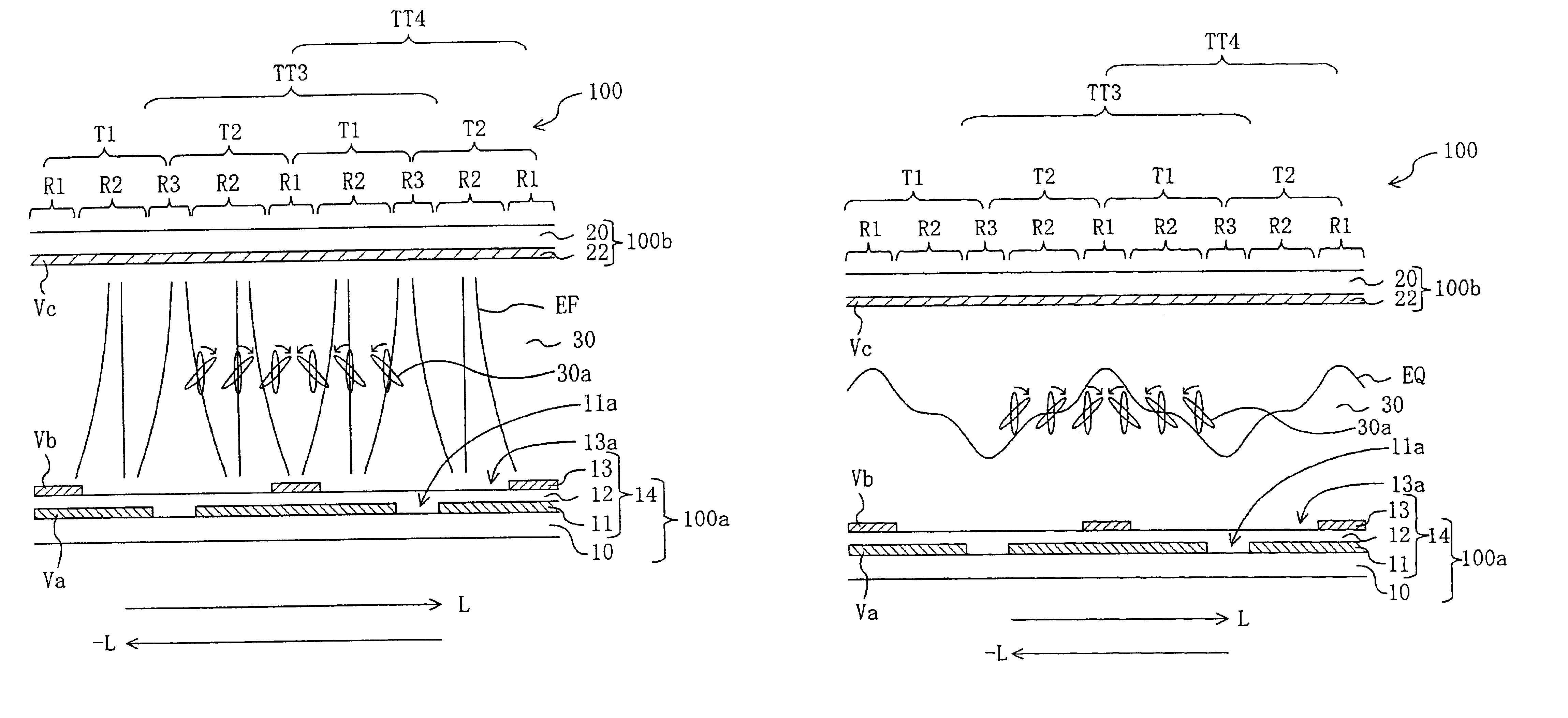
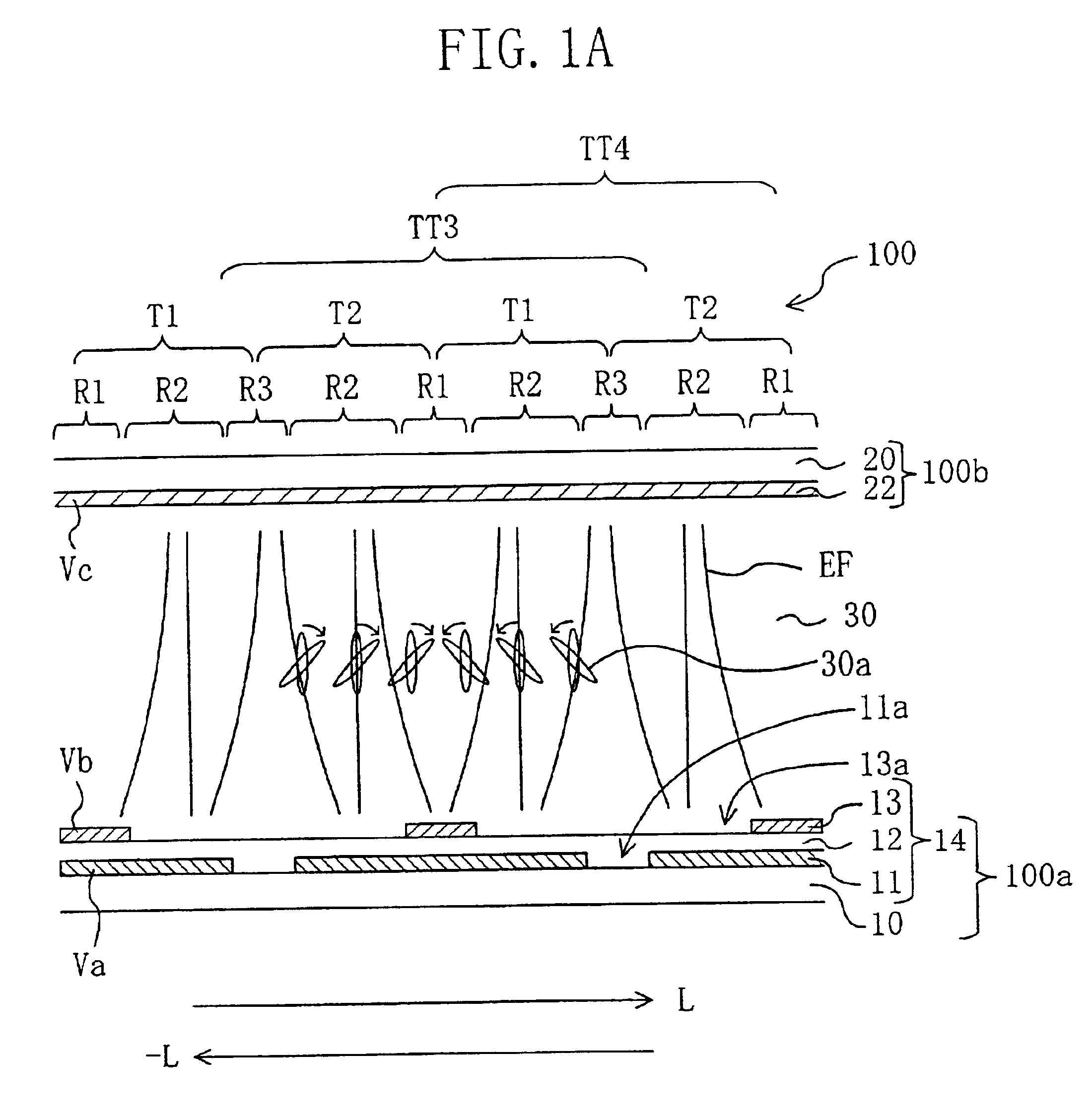
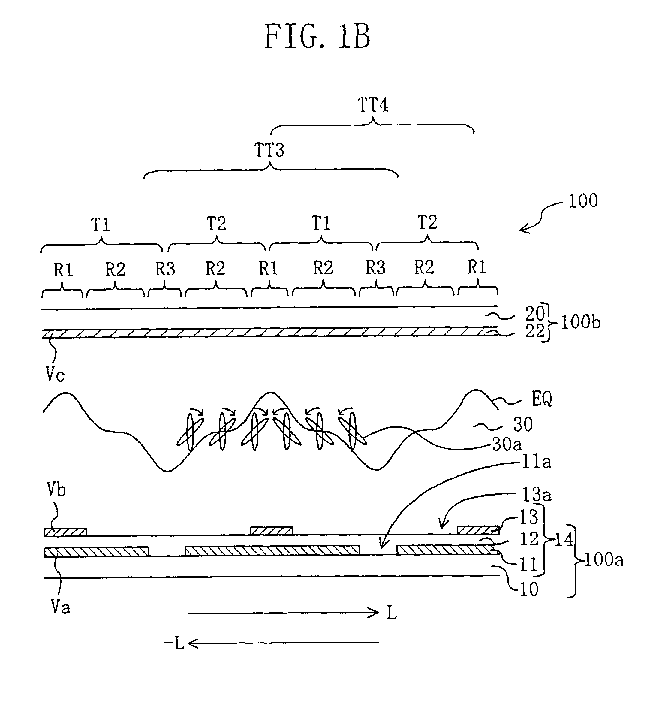
[0073]Hereinafter, preferred embodiments of the present invention will be described with reference to the accompanying drawings. First, the electrode structure of the liquid crystal display device of the present invention and the function thereof will be described.

[0074]In the present specification, a region of a liquid crystal display device corresponding to a “pi...


PUM


Abstract

A first electrode 14 provided in a liquid crystal display device of a vertical alignment mode includes, for each picture element region, a lower conductive layer 11, a dielectric layer 12 covering the lower conductive layer 11, and an upper conductive layer 13 provided on one side of the dielectric layer 12 which is closer to a liquid crystal layer 30. The upper conductive layer 13 includes an upper layer opening 13a, and the lower conductive layer 11 includes a lower layer opening 11a, thus forming first, second and third regions (R1, R2, R3) having gradually decreasing electric field strengths. Liquid crystal molecules 30a of the liquid crystal layer 30 in an orientation-regulating region T1 in which the first, second and third regions are arranged in this order in a predetermined direction change the orientation direction thereof so that they are inclined in a single direction in the presence of an applied voltage.

Description

BACKGROUND OF THE INVENTION[0002]The present invention relates to a liquid crystal display device. More specifically, the present invention relates to a liquid crystal display device having a wide viewing angle characteristic.[0003]A liquid crystal display device is a flat display device with advantageous features such as a reduced thickness, a reduced weight, a reduced power consumption, etc. However, a problem of a liquid crystal display device is that the appearance of the displayed image varies depending upon the direction from which it is viewed, i.e., the “viewing angle dependency” is substantial. The substantial viewing angle dependency of a liquid crystal display device is primarily due to the fact that liquid crystal molecules having a uniaxial optical anisotropy are uniformly oriented in the display plane.[0004]An effective method to improve the viewing angle characteristic of a liquid crystal display device is to produce a so-called “multi-domain orientation” by forming a...

Claims


Application Information

Patent Timeline
IPC IPC(8): G02F1/13G02F1/1333G02F1/1343G02F1/139G02F1/1337
CPCG02F1/133707G02F2201/128G02F1/1393G02F1/134336G02F1/1337
Inventor SHIMOSHIKIRYO, FUMIKAZU
Owner SHARP KK
Why Eureka
Try Eureka