
Method and apparatus for ultra-fast aperture exposure

a technology of aperture exposure and aperture shutter, applied in the field of aperture shutter, can solve the problems of affecting the performance of exposure action, damage or destruction of sensitive detection or measurement instruments, and affecting the accuracy of measurement and evaluation, so as to achieve the effect of dramatically reducing the acceleration required for exposure action

Inactive Publication Date: 2005-02-01
TEAM SPECIALTY PROD
View PDF19 Cites 13 Cited by
  • Summary
  • Abstract
  • Description
  • Claims
  • Application Information

AI Technical Summary

Benefits of technology

[0019]An advantage of the invention is the minimization of dynamic loading which, in conventional rotary shutter mechanisms, results from the application of high impulse forces to the shutters to cause their rapid acceleration. Because each shutter in the present invention is gradually “preset” to an operational angular speed, and the required acceleration to perform exposure action is dramatically reduced. There are attendant benefits in energy efficiency and apparatus stability and durability. Generally, in conventional rotary shutter devices, the shutters must be accelerated from zero velocity to operational speed during the exposure action—which, when the exposure timing desirably is extremely brief, is an intensive operation.
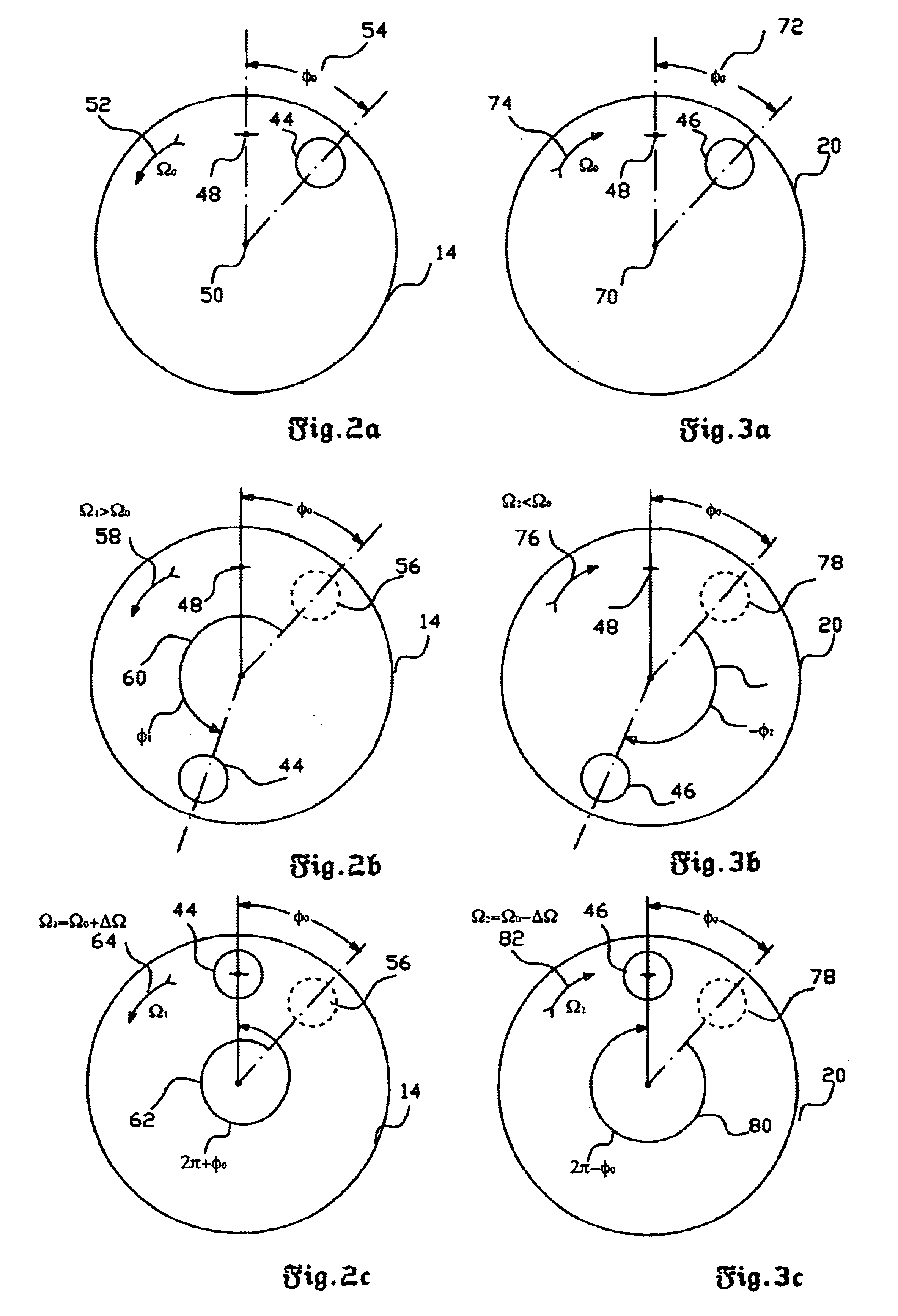
[0020]In contrast in the present invention, to perform an exposure, the shutters are accelerated and decelerated through a full or nearly full (or multiples of full) revolution by adding or subtracting only a small portion of rotational kinetic energy of the discs that are rotated at the synchronous angular speed.

Problems solved by technology

In certain types of research, a defined target may be bombarded with selected energy beams, or may be deliberately subjected to explosion.
Measurement and evaluation often must be accomplished using sensitive and sometimes somewhat fragile yet expensive detection devices.
High-velocity particulate debris may damage or destroy sensitive detection or measurement instruments.
The paramount challenge of such shuttered systems is the provision of sufficient shutter speed to allow the desired measurement to take place, and yet also prevent the passage of deleterious physical debris.
Drawbacks of this solution include the larger size of the system, and the undesirable attenuation of the effect to be measured.
While very fast-acting, such explosive-driven shutters pose obvious disadvantages.

Method used


Image

  • Method and apparatus for ultra-fast aperture exposure
  • Method and apparatus for ultra-fast aperture exposure
  • Method and apparatus for ultra-fast aperture exposure

Examples


Embodiment Construction

ls.

[0029]FIG. 9 is a schematic illustration (partial side sectional view) of an alternative embodiment of the invention, showing an ultra-fast shutter system having three shutters for use in systems featuring more then one aperture;

[0030]FIGS. 10A-C, 11A-C, and 12A-C depict the positional relationships between the rotary shutters of the embodiment shown in FIG. 9 as they move through the opening cycle; and

[0031]FIGS. 13A-C, 14A-C, 15A-C depict the positional relationships between the rotary shutters of the embodiment shown in FIG. 9 as they move through the closure cycle.

DESCRIPTION OF THE PREFERRED EMBODIMENTS (BEST MODES FOR CARRYING OUT THE INVENTION)

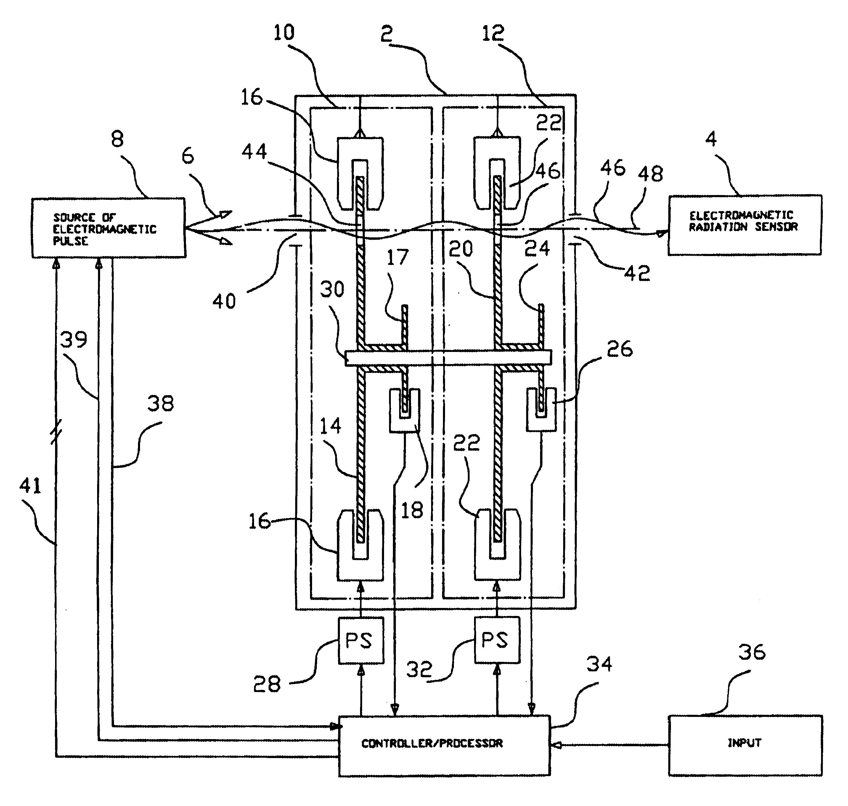
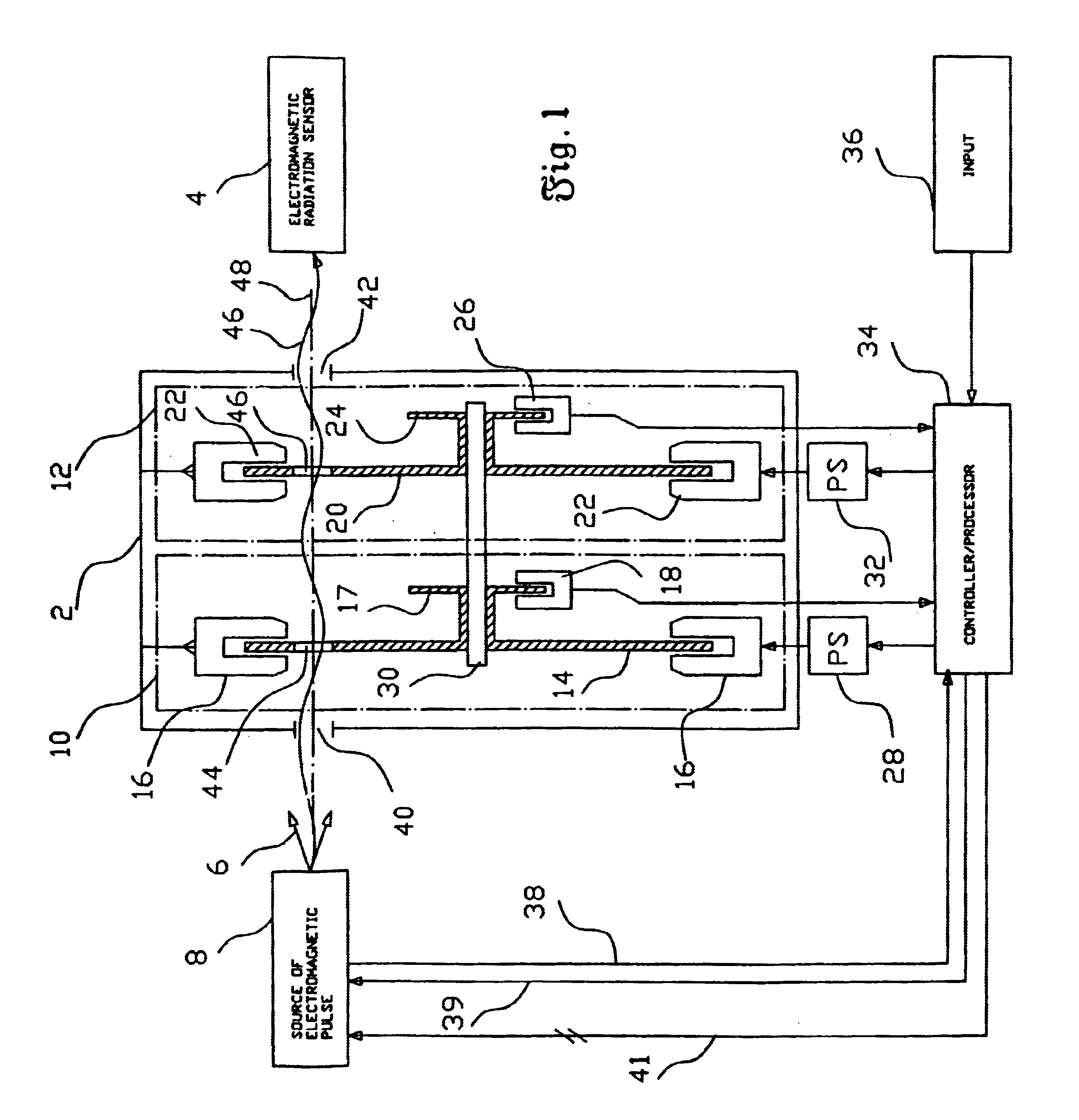
[0032]The invention relates to a method and apparatus to perform a fast aperture exposure, particularly for use in an apparatus for protecting diagnostic equipment from blast damage by rapidly interposing rotary shutters between the equipment and blast area or origin. The apparatus of the invention is an ultra-fast, electrically acti...


PUM


Abstract

An apparatus and method for extremely fast opening and closing of an exposure path or optical axis. Two disk-shaped shutters are coaxially rotated in opposite directions at an initial synchronous speed so as to dynamically align openings in the discs at an angular position offset from the exposure path. The angular speeds of two of the disks are selectively increased and decreased to dynamically align the openings with the exposure path. A third masking disk may be provided, which rotates coaxially with the other two at a constant angular speed less than the angular speeds of the other two disks, to permit the invention to rapidly open and close two or more separate optical paths.

Description

BACKGROUND OF THE INVENTION[0002]1. Field of the Invention (Technical Field)[0003]The present invention relates to aperture shutters, particularly to fast mechanical shutters, and specifically to an apparatus and method for realizing regulated, ultra-fast, opening and closing of a system aperture.[0004]2. Background Art[0005]There was for some time a need in the arts of both still photography and motion-picture making to provide shutter devices for the rapid opening and closing of a camera aperture for the purpose of exposing the film. Increased technological sophistication in the movie making art, in particular, has resulted in the improvisation of a number of optical shutter devices. Representative patents in this field include U.S. Pat. No. 3,735,687 to Park, U.S. Pat. No. 4,301,476 to Keller et al., U.S. Pat. No. 4,536,069 to Kunica, U.S. Pat. No. 4,571,629 to Horio et al., U.S. Pat. No. 4,581,515 to Egashira, U.S. Pat. No. 4,576,456 to Okino et al., U.S. Pat. No. 4,743,108 to V...

Claims


Application Information

Patent Timeline
IPC IPC(8): G02B26/04G02B26/02
CPCG02B26/04
Inventor DJACHIACHVILI, IOURI N.
Owner TEAM SPECIALTY PROD
Learn More