Method and apparatus for an optical multiplexer and demultiplexer with an optical processing loop

a multi-channel, optical processing loop technology, applied in the field of optical filters, can solve the problems of limiting factors such as noise and inter-channel interference, and the requirements for optical filters used in any of these applications are very demanding, and achieve the effect of improving the integrity of optical signals

Inactive Publication Date: 2005-02-01
II VI DELAWARE INC
View PDF13 Cites 13 Cited by
  • Summary
  • Abstract
  • Description
  • Claims
  • Application Information

AI Technical Summary

Benefits of technology

In general, an optical device is provided that can be used in a range of telecommunications applications including optical multiplexers/demultiplexers and optical routers. The optical device split and combines optical signals of frequency division multiplexed optical communication channels which are evenly spaced apart in frequency from one another. The optical device includes an optical processing loop which allows mul

Problems solved by technology

The requirements for optical filters used for any of these applications are very demanding.
Various devices, such as multi-stage band and comb splitters, have been proposed to fill these new demanding requirements and none are fully satisfactory.
In either case, noise and inter-channel interference are limiting factors in the handling of increasingly narrow band pass requirements.
Multi-layer thin-fil

Method used


Image

  • Method and apparatus for an optical multiplexer and demultiplexer with an optical processing loop
  • Method and apparatus for an optical multiplexer and demultiplexer with an optical processing loop
  • Method and apparatus for an optical multiplexer and demultiplexer with an optical processing loop

Examples


Embodiment Construction

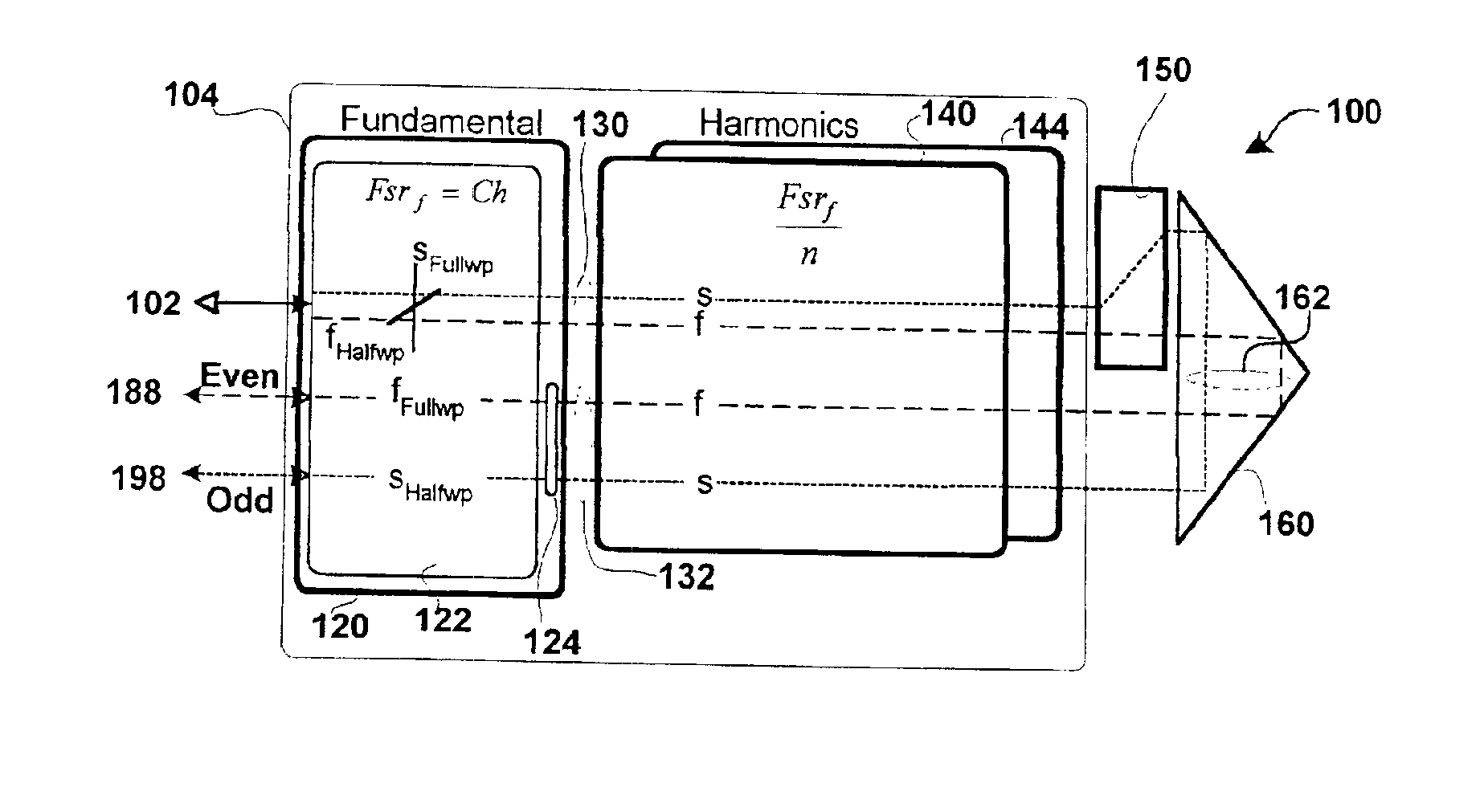
An optical device is disclosed that can be used in a range of telecommunications applications including optical multiplexers / demultiplexers and optical routers. The optical device includes an optical processing loop which allows multi-stage performance characteristics to be achieved with a single physical filtration stage. Optical processing on the first leg and second legs of the loop is asymmetrical thereby improving the integrity of the optical signals by effecting complementary chromatic dispersion for each channel on the first and second legs.

FIG. 1 is a hardware block diagram of an embodiment of the optical mux / demux 100 with an optical processing loop 130,162,132 formed by a single stage 104 optically coupled to a splitter / combiner 150 and retro reflector 160. The mux / demux is designed to operate on the narrowly spaced frequency division multiplexed channels of a telecommunications grid. These channels may be spaced apart in frequency at 50 GHz intervals or less. The mux / demu...


PUM


Abstract

An optical device that can be used in a range of telecommunications applications including optical multiplexers/demultiplexers and optical routers. The optical device includes an optical processing loop which allows multi-stage performance characteristics to be achieved with a single physical filtration stage. Optical processing on the first leg and second legs of the loop is asymmetrical thereby improving the integrity of the optical signals by effecting complementary chromatic dispersion on the first and second legs. In an embodiment of the invention the optical device includes a fundamental filter cell, a retro reflector and a splitter/combiner. The fundamental filter cell filters optical signals propagating on each of two legs of an optical loop which intersects the fundamental filter cell. The fundamental filter cell operates as a full waveplate to the odd set of channels and a half waveplate to the even set of channels on a selected one of the two legs and as a half waveplate to the odd set of channels and a full waveplate to the even set of channels on a remaining one of the two legs. The retro reflector optically couples with the fundamental filter cell to reflect the optical signals from one of the two legs to an other of the two legs to form the optical loop. The splitter/combiner optically couples between the fundamental filter cell and the retro reflector to split or combine the odd set of channels and the even set of channels depending on the propagation direction of the optical signals along the optical loop.

Description

BACKGROUND1. FieldThe present disclosure generally relates to optical filters and more particularly to optical filters for optical fiber communication networks.2. Description of the Related ArtThe Synchronous Optical Network (SONET) standard defines a hierarchy of multiplexing levels and standard protocols which allow efficient use of the wide bandwidth of fiber optic cable, while providing a means to merge lower level DS0 and DS1 signals into a common medium. Currently optical communication is accomplished by what is known as “wavelength division multiplexing” (WDM), in which separate subscriber / data sessions may be handled concurrently on a single optic fiber by means of modulation of each of those subscriber data streams on different portions, a.k.a. channels, of the light spectrum.The spacing between channels is constantly being reduced as the resolution and signal separation capabilities of multiplexers and de-multiplexers are improved. Current International Telecommunications ...

Claims


Application Information

Patent Timeline
IPC IPC(8): G02B6/34H04J14/02H04Q11/00
CPCG02B6/272G02B6/29352H04J14/02H04Q11/0005H04Q2011/0075H04Q2011/0015H04Q2011/0016H04Q2011/0026H04Q2011/0009
Inventor XIE, PINGBETTMAN, R. BRADRONG, HAISHENGZHANG, KEVINMAO, YALANWANG, WEIWU, SIMON YUANXIANG
Owner II VI DELAWARE INC
Why Eureka
Try Eureka