Eureka AIR delivers breakthrough ideas for toughest innovation challenges, trusted by R&D personnel around the world.

Digital equalizing method and radio communication receiver implementing said method

a radio communication receiver and equalization method technology, applied in the field of digital equalization of signals, can solve the problems of complex implementation of the second equalization method, and achieve the effect of lower values and higher values of p

Inactive Publication Date: 2005-02-01
APPLE INC
View PDF5 Cites 50 Cited by
  • Summary
  • Abstract
  • Description
  • Claims
  • Application Information

AI Technical Summary

Benefits of technology

The implementation of the second equalization method is generally more complex than the first. In each particular case, the choice of the number p allows the b

Problems solved by technology

The implementation of the second equalization method is generally more complex than the first.

Method used


Image

  • Digital equalizing method and radio communication receiver implementing said method
  • Digital equalizing method and radio communication receiver implementing said method
  • Digital equalizing method and radio communication receiver implementing said method

Examples


Embodiment Construction

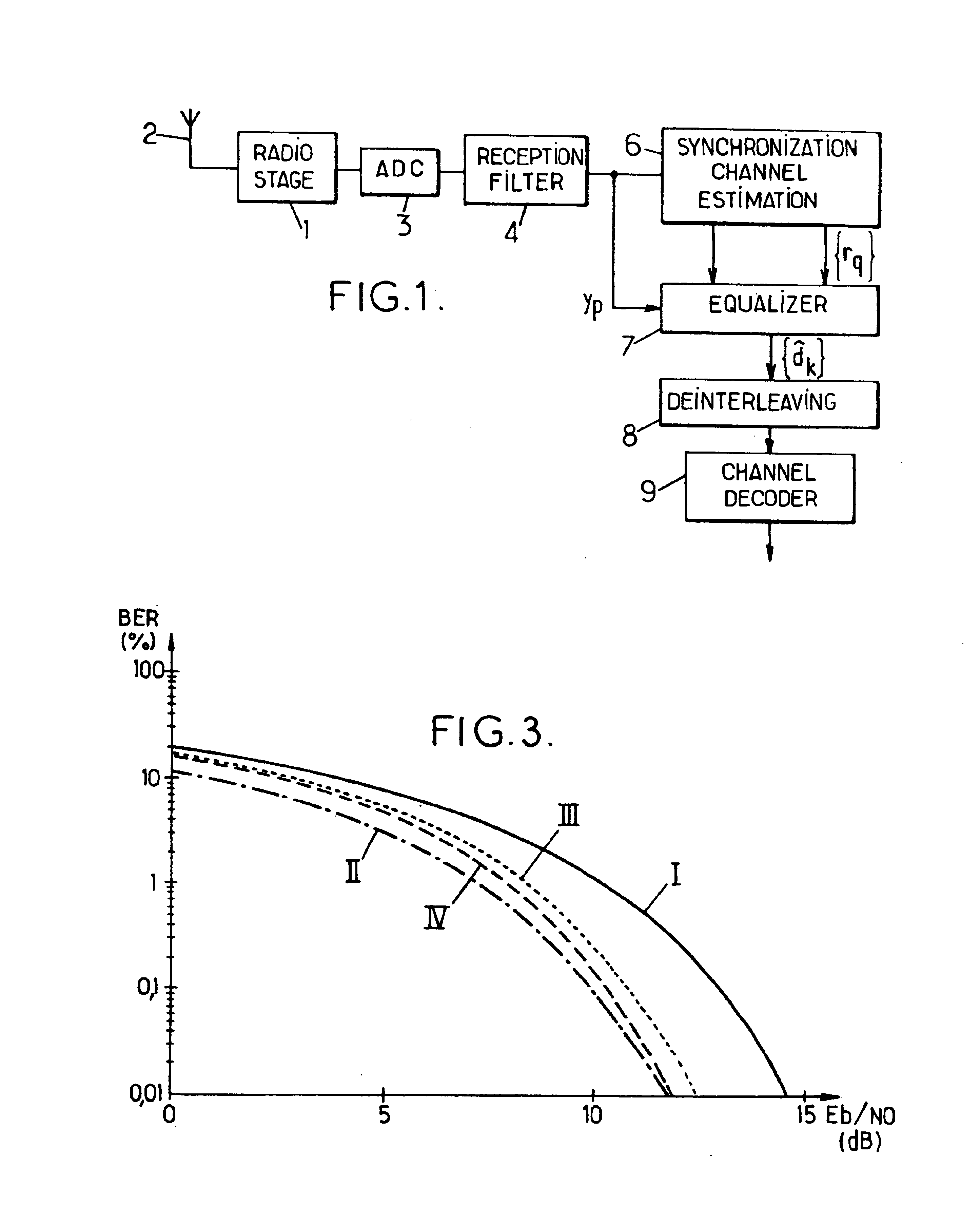
The receiver represented in FIG. 1 comprises a radio stage 1 which receives the signal picked up by antenna 2 and converts it to the baseband. The baseband signal is digitized by the analog-to-digital converter (ADC) 3 and fed to the reception filter 4. Filter 4 provides matched filtering with respect to the signal shaping by the transmitter. It delivers a digital signal at a rate of one complex sample per transmitted symbol.

The digital signal is fed to a demodulator comprising, on the one hand, a synchronization and channel estimation module 6 and, on the other hand, an equalizer 7.

The synchronization and channel estimation are, for example, performed conventionally by means of a synchronization sequence included by the transmitter in each signal frame. Detection of this sequence, known to the receiver, allows, on the one hand, the receiver to be synchronized relative to the temporal structure of the transmitted frames, and on the other to estimate the impulse response r=(r0, r1, ....


PUM


Abstract

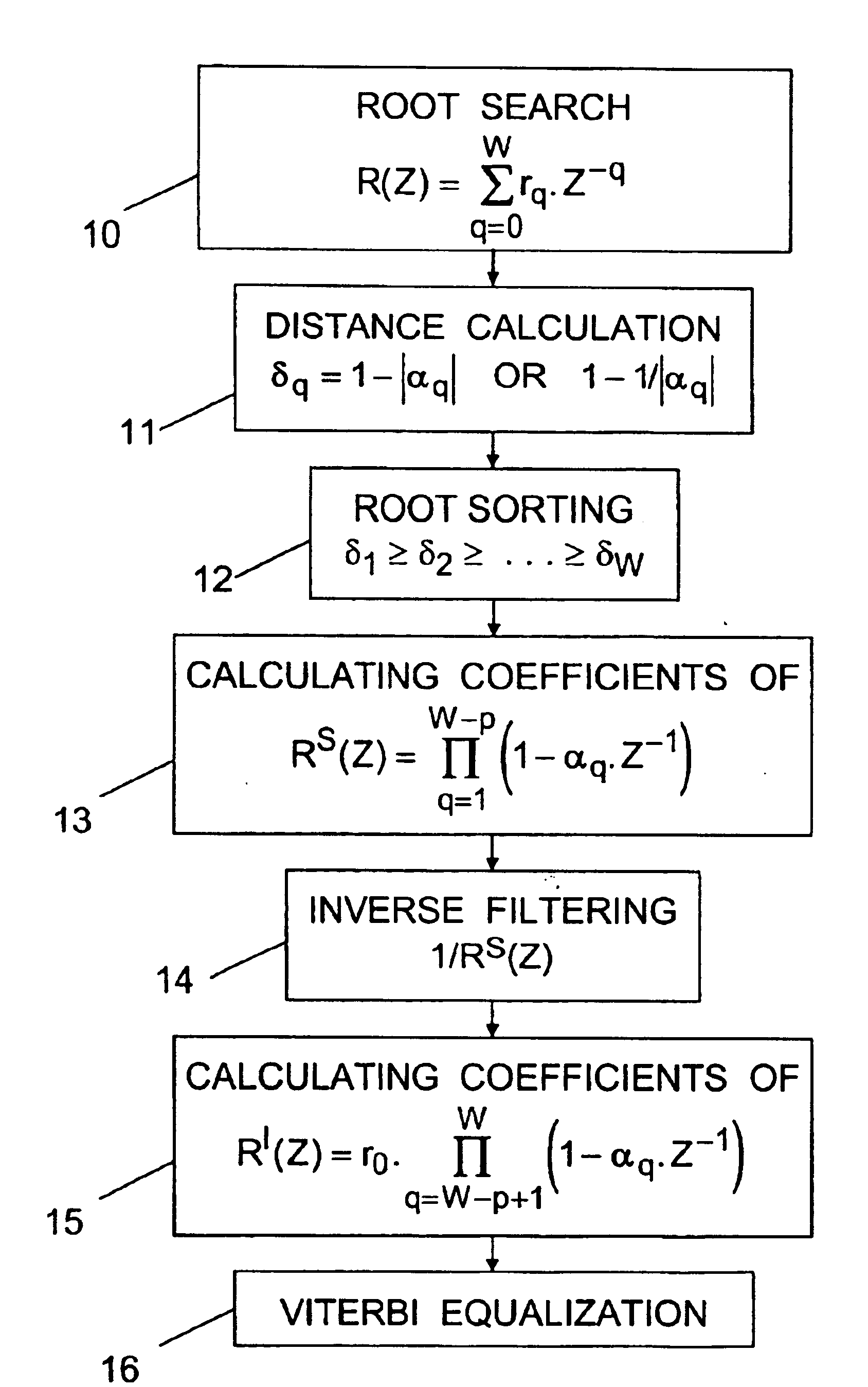
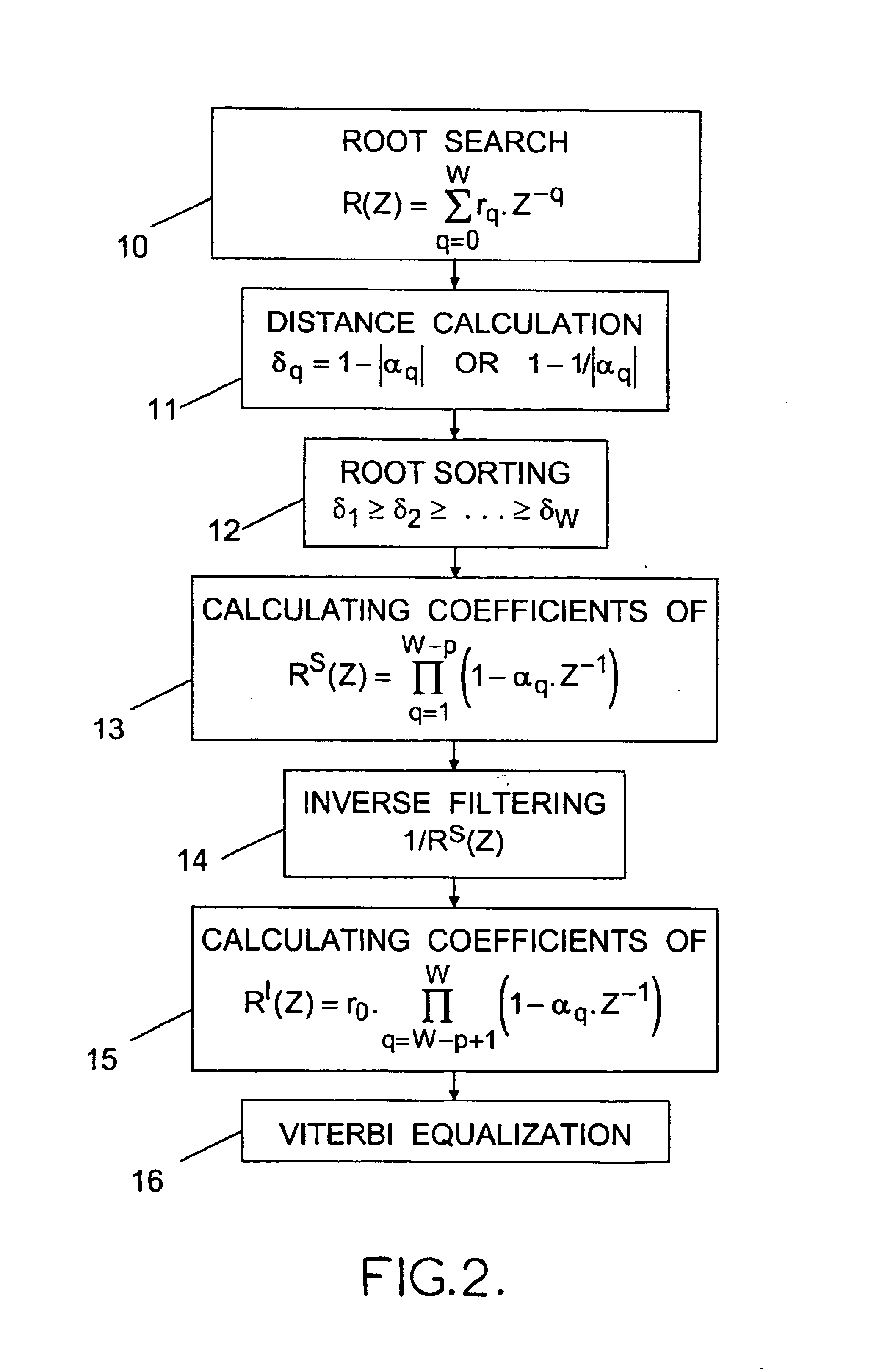
For processing samples of a signal received via a channel represented by an impulse response of W−1 coefficients, the method comprises: determining the W roots of the Z-transform of the channel impulse response; producing an intermediate signal by equalizing the received signal by a zero-forcing method or the like based on an impulse response whose Z-transform is a Z−1 polynomial of degree W-p having as roots those of the W roots which are furthest from the unit circle of the complex plane; and then obtaining estimations of the transmitted signal symbols by applying a Viterbi-type equalization method or the like based on an impulse response whose Z-transform is a Z−1 polynomial of degree p having as roots those of the W roots which are nearest to the unit circle.

Description

BACKGROUND OF THE INVENTIONThe invention concerns the digital equalization of signals. It has important applications in the field of radio communications.The method is applied to the processing of a signal received from a transmitter over a channel between transmitter and receiver, whose response is known or has been estimated beforehand. One of the main issues is then that of the compromise between the performance of the equalizer and its complexity.A complete maximum likelihood estimation of the transmitted signal is possible, for example by employing the Viterbi algorithm (see G. D. Forney Jr.: The Viterbi Algorithm, Proc. of the IEEE, Vol. 61, No. 3, March 1973, pages 268-278). Nevertheless, as soon as the impulse response of the channels becomes long or the number of possible discrete values becomes large, the exponentially increasing complexity of these methods renders them impracticable.We consider the case of a radio communications channel used for the transmission of a sign...

Claims


Application Information

Patent Timeline
IPC IPC(8): H03H7/30H04L27/22H04B3/06H04L25/03H04B7/005H04L27/01
CPCH04L25/03203H04L25/03159
Inventor DORNSTETTER, JEAN-LOUISRACHED, NIDHAM BENBONHOMME, CORINNE
Owner APPLE INC
Why Eureka
Eureka Blog
Learn More