Methods for identification and verification using digital equivalent data system

a technology of digital equivalent and data system, applied in the direction of material analysis using wave/particle radiation, material analysis by secondary emission, instruments, etc., can solve the problems of inconvenient direct part (or object) marking (dpm), inefficient manual data collection and keyed data entry, and inability to identify and verify objects. , to achieve the effect of simple and easy us

Inactive Publication Date: 2005-02-01
NASA +1
View PDF64 Cites 70 Cited by
  • Summary
  • Abstract
  • Description
  • Claims
  • Application Information

AI Technical Summary

Benefits of technology

The invention provides apparatus and methods in which one or more elemental taggants that are extrinsically placed in an object are detected by x-ray fluorescence analysis to identify or authenticate the object. The taggant is manufactured as part of the object or the taggant is placed into a coating, packaging, label, or otherwise embedded onto the object for the purpose of later verifying the

Problems solved by technology

Recognizing that manual data collection and keyed data entry were inefficient and error-prone, many industries adopted bar code technology in the mid 1980s.
Bar codes were determined, however, to not be suitable for direct part (or object) marking (DPM).
These marking methods, originally designed to apply human-readable markings, did not successfully apply micro-size ({fraction (1/32)}-inch to {fraction (15/64)}-inch square), high-density machine-readable symbols.
Their manual operations also added to the large number of data transposition errors.
Unfortunately, many of the non-DPM methods for identifying and authenticating objects are unsatisfactory for several reasons.
First, they are often difficult and time-consuming.
In other instances, the apparatus are often expensive, large, and difficult to operate.
Finally, due to the unsophisticated nature of the methods,

Method used


Image

  • Methods for identification and verification using digital equivalent data system
  • Methods for identification and verification using digital equivalent data system
  • Methods for identification and verification using digital equivalent data system

Examples


Embodiment Construction

The following description provides specific details in order to provide a thorough understanding of the invention. The skilled artisan will understand, however, that the invention can be practiced without employing these specific details. Indeed, the invention can be practiced by modifying the illustrated apparatus and method and can be used in conjunction with apparatus and techniques conventionally used in the industry. For example, the invention is described with respect to apparatus and methods for identifying and tracking / tracing objects using taggants in combination with data matrix symbols. The invention described below, however, could be easily modified to be used in combination with any 2D symbols. Indeed, the invention could be modified to be used with any DPM technologies.

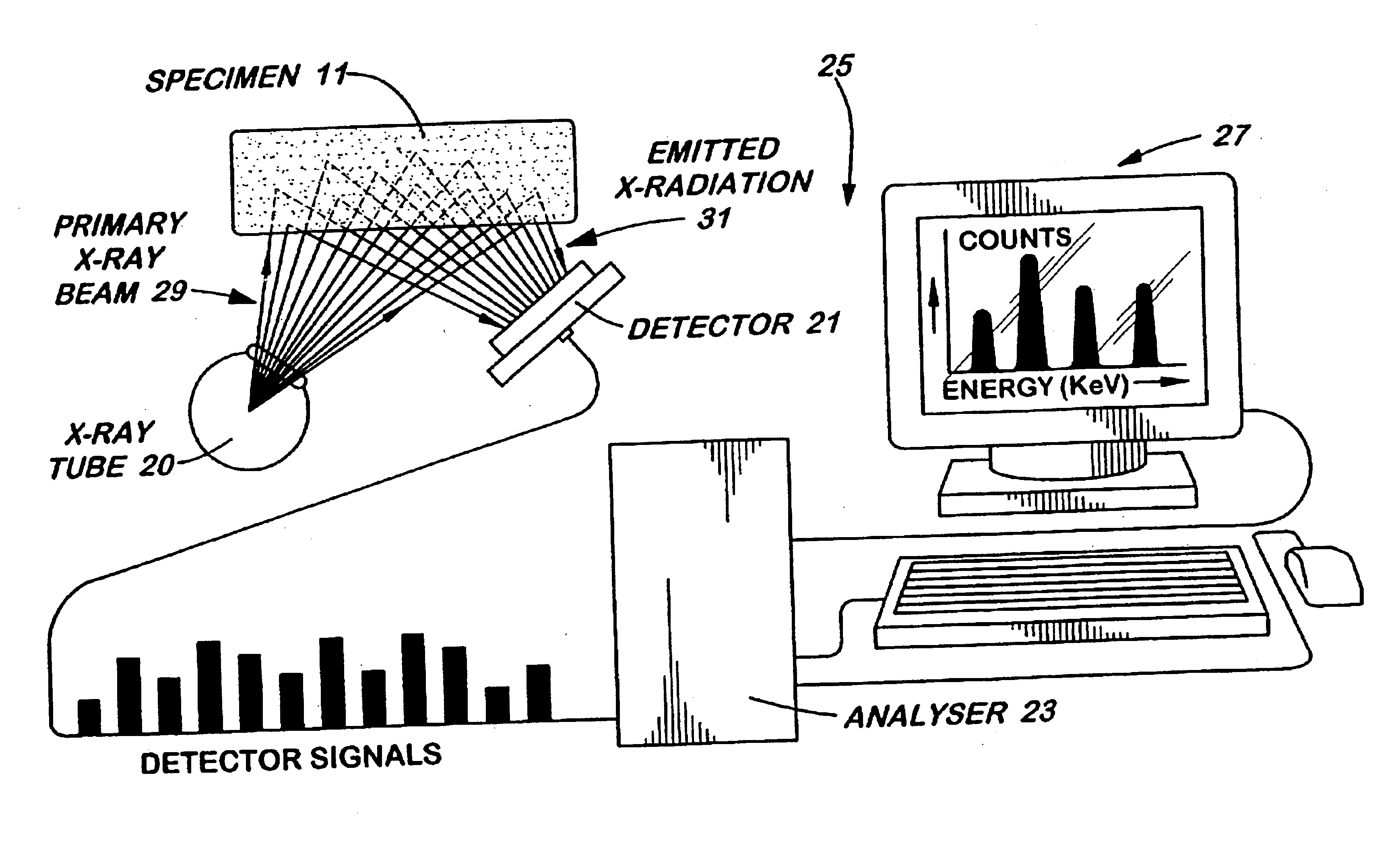
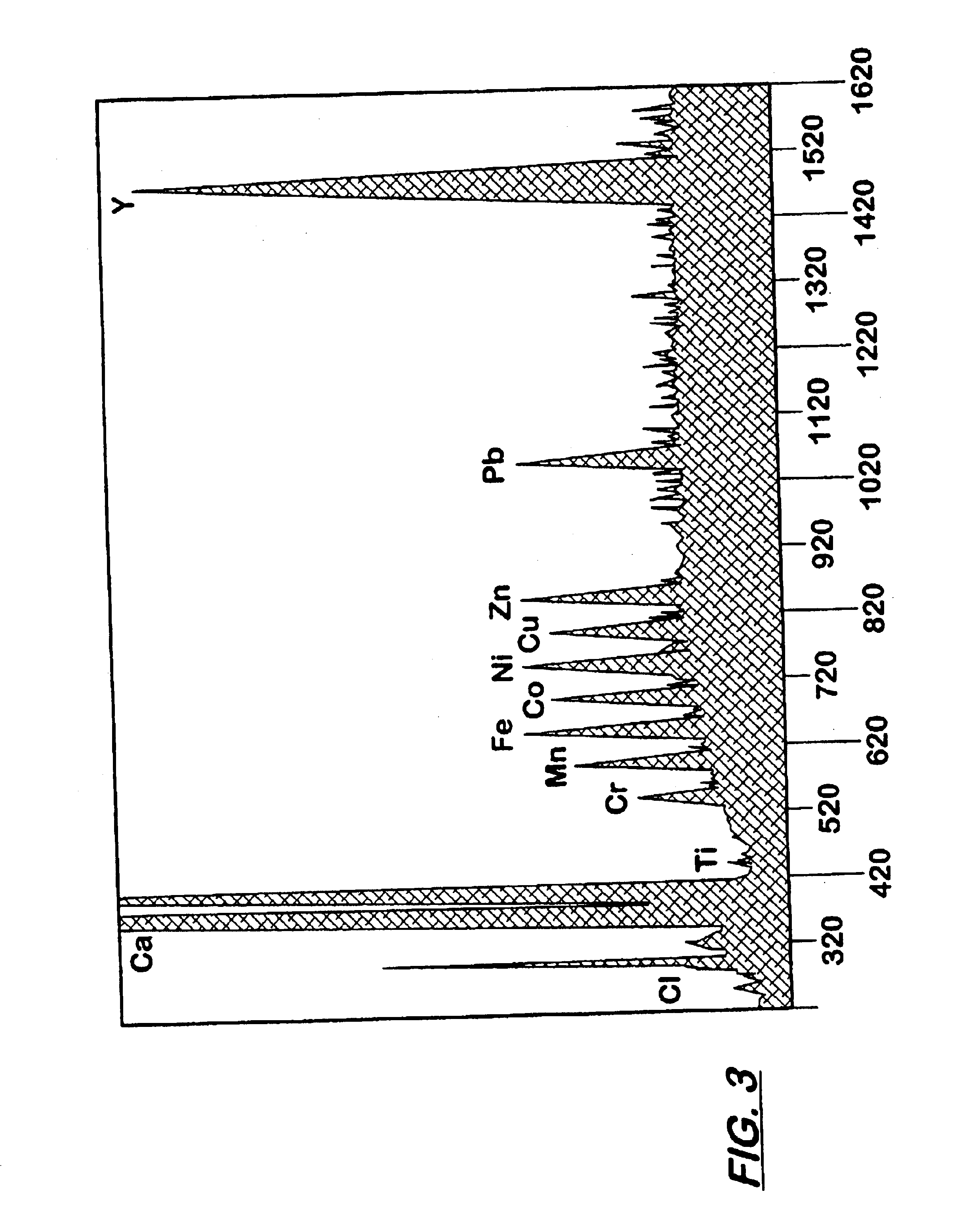
The invention uses x-ray fluorescence analysis to detect at least one elemental taggant that has been extrinsically added to an object. With x-ray fluorescence (XRF) analysis, x-rays produced from electr...


PUM

PropertyMeasurementUnit
Energyaaaaaaaaaa

Abstract

Apparatus and methods in which one or more elemental taggants that are extrinsically placed in an object are detected by x-ray fluorescence analysis to identify or authenticate the object are described. The taggant is manufactured as part of the object or the taggant is placed into a coating, packaging, label, or otherwise embedded onto the object for the purpose of later verifying the presence or absence of these elements by x-ray fluorescence. The taggant is then analyzed by XRF and the analysis is then converted into a 2D symbol format that can be used in various security and authentication applications. By using x-ray fluorescence analysis, the apparatus and methods of the invention are simple and easy to use, without the limitations experience by current anti-counterfeiting technologies.

Description

FIELD OF THE INVENTIONThe invention generally relates to apparatus and methods for identification and verification. More particularly, the invention relates to apparatus and methods for detecting an element or elements extrinsically added to an object by using x-ray fluorescence. Even more particularly, the invention related to apparatus and methods for detecting an element extrinsically added to an object by using X-ray fluorescence to identify and authenticate that object.BACKGROUND OF THE INVENTIONThere has been significant interest in apparatus and methods for identifying and verifying various articles or products (or objects) such as explosives, ammunition, paint, petroleum products, and documents. Known methods used to identify and verify such objects generally involve adding and detecting materials like microparticles, bulk chemical substances, and radioactive substances. Similar marking methods include inks that are transparent in visible light are sometimes applied to objec...

Claims


Application Information

Patent Timeline
IPC IPC(8): G01N23/22G01N23/223
CPCG01N23/223G01N2223/076
Inventor SCHRAMM, HARRY F.KAISER, BRUCEKUHLMAN, ROBERT D.HOWE, THERESESHANNON, ROBERTWHEELER, KEN
Owner NASA
Why Eureka
Try Eureka